


A Delta-type Opposed-piston Engine
Page 68
If you've noticed an error in this article please click here to report it so we can fix it.
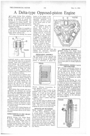
ANengine having three cylinders, each containing a pair of opposed pistons, is disclosed in patent No. 705,780, by B. Fiala-Fernbrugg, Am Modenapark 10, Vienna, Austria. The cylinders are laid out in delta formation, that is, their axes form the sides of an equilateral triangle.
Using such a layout, it is possible to obtain the four events of the Otto cycle in one turn of the crankshaft, and the engine shown achieves this.
Referring to the drawing, the central crankshaft carries a main connectingrod to which the other two are pivotally attached. Each rod is connected to a rocker linkage, one of which is shown generally at I. The rocker assembly is a rather complex system of levers and is best considered as being one rocker mounted on another. Each rocker is connected with its neighbouring piston in the conventional manner.
The working cycle is as follows; starting from the end of the exhaust stroke, the two pistons are almost touching in the region of the exhaust belt (2). They then move leftwards together but the left-hand one rapidly accelerates and uncovers the inlet belt (3). The new charge is then drawn in by the partial vacuum created between the separating pistons.
Both pistons then reverse and move rightwards, the left-hand one moving the faster and compressing the charge; this is fired at mid-stroke in a 10-mm. compression space. The power stroke fellows and forces the pistons apart.
The right-hand piston eventually uncovers the exhaust belt, but the lefthand piston does not reach the inlet belt. Instead, it reverses its direction earlier and follows up the other piston to effect an exhaust stroke.
The patent gives timing diagrams of the various events and both geometric and constructional details of the rocker assembly.
IMPROVEMENTS IN DISC BRAKE CONSTRUCTION
'ROM Girling, Ltd., Kings Road, 1. TYscley, Birmingham, 11, comes patent No. 706,050 dealing with the design of disc brakes. The novelty is in constructional details rather than in principle, the object being to facilitate manufacture and reduce weight. A
534 feature of the design is that the hydraulic cylinders can be separately machined a n d assembled, and then inserted in the carrier plate as complete units.
Three cylinders are used, one of which is shown in section. The carrier is a channel-section be (1) which is bored to receive the cylinder units (2). To prevent spreading of the channel section when hydraulic force is applied, it is bridged by a number of horseshoe-shaped pressings (3). These are placed over the channel and then welded or brazed in place.
The cylinders are secured in bored holes in the beam by a bayonet-type joint having three projections and three slots; this explains the apparently impossible assembly shown at point 4.
PISTON-RING ASSEMBLY
A COMPOSITE piston ring that not fl only presses on the cylinder wall but also on the bottom of the piston groove, is described in patent No.
705,123. (Ramsey Corporation, St. Louis, Missouri, U.S.A.) The drawing shows a section of the proposed ring in place in the piston groove. It is built up from units of coiled, flat, steel strip, and each unit consists of two turns. The strip is " joggled " where it passes from one level to the next.
Five of these units are placed in the groove, the top, middle and bottom ones being biased to press on the cylinder walls. , The others are inwardly sprung gripping the groove on its inner face.
ROAD-TO-MR TRANSPORT
THE FAIREY AVIATION CO., LTD., Hayes, Middlesex, disclose in several patents a complete system for co-ordinating road and air traffic. The aim is to transfer loads from road vehicle to aircraft and vice versa with the minimum of labour and time. Containers form the basis of the system, and vehicles and aircraft are standardized to ensure their rapid transfer. The patents are numbered 706,611, 706,612 and 706,613.
DISC-BRAKE DETAILS CROM Girling, Ltd., King's Road, TyseIey, Birmingham, comes patent No. 703,213, which deals with improvements in disc brake design. In this case, the friction pads, instead of being circular, are of segmental form. They are, however, pressed into braking contact by three pairs of circular hydraulic pistons.
A FREE-SLIDING NEEDLE VALVE FOR INJECTORS TO eliminate considerable friction is the object of a modified design of injector needle-valve shown in patent No. 705,129, by B. Tavola, 21 Via Benvenuto Cellini, Milan, Italy. Instead of the needle being guided in a closefitting bore, it is mounted on axially moving ball bearings.
Referring to the drawing, the valve is guided by the two sets of balls (1 and 2), which can move in an up-and-down direction in annular races. The valve is lifted by the fuel pressure in the usual way. and all leakage is prevented by the interposition of a synthetic-rubber diaphragm (3). This is clamped round its peripheral portion by a screwed sleeve (4) and is centrally gripped between a shoulder on the valve-stem and spring collar 5.