


Diagnosing Electrical Faults
Page 66
Page 67
If you've noticed an error in this article please click here to report it so we can fix it.
How, by Adopting the Correct Procedure, Otherwise Elusive Electrical Troubles Can be Quickly Detected Without the Use of Expensive Equipment By W. Topping
DIAGNOSIS of electrical faults and repair of the equipment can sometimes be very complex, particularly when the job is urgent and there is little time for thought. Faulty diagnosis can waste many hours before the repair can be tackled. Always use the step-by-step method of elimination for diagnosis. Think in stages, and apply the use of test meters in stages also.
Indispensable aids to testing are a good moving-coil D.C. voltmeter, reading up to 4() V., and a reliable 30-30 ammeter, which. should be accurate to within one half of an amp. For continuity testing an accurate ohmmeter is the best instrument, but a test-lamp and buzzer form an alternative which can serve the same purpose. Spare lengths of cable with crocodile clips fitted to each end (or "jumper" cables) are very useful when dealing with wiring problems.
Charging-system Faults
Using an auxiliary "jumper," current can be taken from the live battery terminal and supplied to any part of a suspected circuit. Faults in the charging system are amongst the most common causes of trouble, the more puzzling faults being generally those related to voltageregulator circuits.
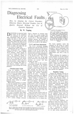
When testing dynamos, it is useful to take the example of the standard two-terminal Lucas generator, the tests for the twoand three-terminal machines being the same. The connections are shown in Fig. 1.
First remove the external wires to the F and D terminals, then bridge the dynamo terminals as shown, and connect a voltmeter between the linked terminals and "earth." On a 12-V. system, voltages obtained from a dynamo in working order will vary, but a good average with the engine running at normal speed is up to 40 V. This high voltage is obtained because the dynamo is running on an open-circuit and the current has no path to the battery.
C.A.V. and Lucas Instruments
The C.A.V. two-brush charging systems work with the field circuit of the dynamo connected in the reverse manner to that of the Lucas unit. Instead of the internal end of the dynamo field coil being connected to earth, the coil is connected directly to the positive brush. Thus, if the external or other end of the field coil be connected to the positive (D) terminal, no current will flow through the fields.
It follows that to test a C.A.V. two-terminal dynamo the voltmeter will be connected to the positive terminal. Terminal F must be connected to earth so that current will flow through the field from the internal positive brush and to earth through the external connection fitted by the tester. Variations of voltmeter connections for different types of dynamo are shown in Fig. 2.
Before testing a dynamo it is necessary to ensure that its driving belt is not slipping. Belt slip can be deceptive, particularly when oil or grease forms a skin of lubricant on the driving surfaces of the belt. It will then slip only when the dynamo is working under an abnormal load, such as when the battery is low and the charge rate is high.
Lucas two-brush systems work on the principal that if more current be allowed to flow from D to F, then a bigger field flux is obtained, with a proportionate rise in charge rate.. The Lucas regulator varies the resistance of the circuit by means of vibrating contacts, which connect terminals F and D alternately with a resistance situated in the back of the regulator. This is usually of the single-contact type and is easy to
adjust.
Before adjusting the regulator it is first necessary to test the dynamo and the battery connections and to make sure that the earth wire from the regulator (E) terminal to the vehicle frame is in good condition. Insert a small piece of dry paper between the cut-out points which will " open-circuit" the dynamo. It is the open-circuit voltage setting that controls the regulator.
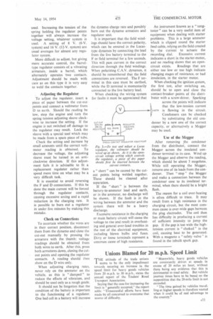
Regulator Testing
Connect the voltmeter from D, or the frame of the regulator, as shown in Fig. 3, and run the engine up to a fairly fast tick-over speed. A. reading of 16 V. should be obtained. More than this is excessive on a normal system, but if in doubt, always check with the makers of the dynamo. Sometimes a slightly higher setting is recommended, but a 16 V. reading should be taken as quite normal on 12-V. systems.
To adjust the voltage setting, the regulator adjusting screw at the back of the regulator frame must be altered. Slacken the lock-nut on the adjusting screw and turn the screw clockwise to increase the voltage or anti-clockwise to reduce it.
The C.A.V.-type regulators are adjusted in much the same manner. The design restricts the flow of the field current to earth, whereas in the Lucas system the flow between F and + terminals is restricted On some models of C.A.V. regulator an open spring adjustment is used. Increasing the tension of the spring holding the regulator points together will always increase the voltage setting, whatever system is used. A setting of 8 V. (6-V. system) and 16 V. (12-V. system) are usual averages for almost any regulator system.
More difficult to adjust, but giving more accurate control, the barreltype regulator consists of a vibrating armature, inside a barrel, which alternately operates two contacts. Adjustment should be made with care as on this type it is very easy to weld the contacts together.
Adjusting the Regulator To adjust the regulator, insert a piece of paper between the cut-out • points and connect a voltmeter from D to earth. Should the reading be low, stop the engine and turn the spring tension adjusting sleeve clockwise to increase the setting. If the engine is not switched off damage to the regulator may result. Lock the sleeve with a special tool which may be made from a spare piece of tube.
Check the setting and increase by small amounts until the correct voltmeter reading is obtained. To decrease the voltage, the adjusting sleeve must be turned in an anticlockwise direction. If this adjustment fails it is advisable to fit a replacement regulator rather than spend more time on what may be a very difficult task.
It is essential to avoid reversing the F and D connections. If this be done the main current will be forced through the regulator contacts, causing excessive arcing and a rapid reduction in the charging rate. It is possible to burn out a regulator in under five minutes by making this mistake.
Check on Connections To ascertain whether the wires are in their correct position, disconnect them from the dynamo and close the cut-out manually by pressing the armature with the thumb; voltage readings should be obtained from both wires to earth. After this, press both armatures down, closing the cutout points and opening the regulator contacts. A reading should then show on the D wire only.
When adjusting charging rates, never rely on the ammeter on the vehicle, as this is " damped " to reduce the effects of vibration, and should be used only as a rough guide.
It should not be forgotten that the condition of the battery is important to the functioning of a regulator. One bad cell in a battery will increase the dynamo charge rate and possibly burn out the dynamo armature and regulator unit.
It is important that the field windings should have the correct polarity, which can be ensured in the Lucastype dynamos by connecting the lead from the live battery terminal to the F or field terminal for a few seconds. This will pass current in the correct direction through the field windings. When polarizing C.A.V. dynamos, it should be remembered that the field connections are reversed. The F terminal in this case must be earthed, while the D terminal is momentarily connected to the live battery lead.
When checking the wiring system for faults it must be appreciated that a " short " can be caused by the cutout points being welded together. These should be cleaned after separation.
If the " short " is between the battery-to-ammeter lead and earth, or in the ammeter, no discharge will be shown. If the fault is in the wiring between the ammeter and the system there will be a heavy
discharge.
Excessive resistance in the charging
or main battery circuit will cause the voltage to rise and result in overheating and general over-load troubles in the rest of the electrical equipment, including blown bulbs and fuses. Dirty or loose terminals represent a common cause of high resistance.
An instrument known as a " tongtester " can be a very useful item of equipment when dealing with starter problems. This is a large ammeter which is clipped round the starter feed cable, relying on the field created by the current to actuate the recording dial. Excessive current indicates a short in the starter-motor, and no reading shows that an open circuit exists. Readings that are either too low or too high indicate changing stages of resistance, or bad insulation, in the starter motor.
When checking the ignition system, the first test, after switching on, should be to open and close the contact-breakerpoints of the distributer with a screw-driver, Sparking across the points will indicate that the low-tension current is flowing in the circuit. Condensers can be checked by substituting the old condenser by a new one of the correct capacity, or alternatively a Megger may be used.
11 EARTH
Use of the Megger
After removing the condenser from the distributor, connect the Megger across the insulated condenser terminal to its case. Wind up the Megger and observe the reading, which should be about 3 megohms. While still operating the Megger, remove one of its leads from the condenser. Then " stop " the Megger and make a connection between the condenser case to its insulated terminal, when there should be a bright flash.
The reason for a coil over-heating is often difficult to trace. It may result from a high resistance in the charging circuit, but the most common cause is over-wide gaps between the plug electrodes. The coil then has difficulty in producing a current of sufficient intensity to jump the gap. If the gap is too wide the hightension current is " choked " in the coil, causing heat to be generated. With a magneto a "safety valve" is found in the inbuilt spark gap.