


Running C.I. Engine on Waste Heavy Oils
Page 34
If you've noticed an error in this article please click here to report it so we can fix it.
rrenable an oil-engined vehicle to e run on waste lubricating oil, or semi-solid vegetable oils, is the object of a special filtering device shown in patent No. 552,107 by R. H. Seddon, 114, Eccles Old Road, Pendleton, Salford 6. The filter is heated to pro.mote throughput of the fuel, and its action is accelerated by the application of pressure to the fuel in the supply tank. A device to prevent clogging of the filter-pad is suggested.
As both heat and pressure are applied to the fuel while it is in the storage tank, a special container must be employed. The drawing shows the tank, with the filtering elements in an attached compartment. Heating is performed by exhaust gases, which enter pipe 8 and first heat the filter by passing through its jacket (6). The gases then traverse heater pipes (3) immersed in the fuel, reach an expansion chamber (4)' and,. finally, make their exit from .the' open end (5).
Air pressure is applied to the tank by a manually operated. pump. or by the small tyre inflator generally carried on modern -'vehicles.' The vertical filters (2), four of which are used, are of the edge-disc type, that is, the kind employing stacks _of thin discs through which the fuel can percolate. Fuel arrives at the exterior of the discs and is forced through-them into their central spaces, whence it flows via a common, collecting cap (1) to the-, pipe (9) leading to the injection pump.
A butterfly valve (7) is located in the exhaust inlet to regulate the work-' Mg temperature; a thermostat• may be used to control this if desired.' Au . Au auxiliary tank of ordinary, clean oil fuel is carried on the vehicle, which can then be started and run until the main tank has become sufficiently heated for filtration to commence. It is to be presumed that, under operating conditions, temperatures Would be so adjusted as to bring the oil being used to the same -level of viscosity as a normal fuel oil.
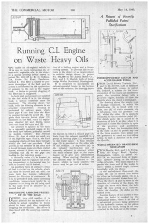
PREVENTING RADIATOR FREEZEUP ON THE ROAD
DURING very cOld weather, it is quite possible for the radiator of a vehicle in actual operation to freeze about its lower part, thus completely stopping the circulation. The driver is then faced with the annoying combina ombina tion tion of a boiling engine and a frozen cooling system. To prevent this occurrence is the object of an improvement in radiator design shown in patent No. 552,188 by the Austin Motor Co., Ltd., and J. C. Haefeli, both of Longbridge Works, Northfield, Birmingham.
It is proposed to incorporate an exhaust-operated heater in the bottom tank of the radiator; the drawittg shows
the layout, in which a branch pipe (3) leads from the exhaust manifold to a .group of heating pipes (1) submerged in the' water. space. A final exhaust pipe (2) is provided on the other side of the radiator. A flap-valve (4) in the exhaust junction-box can be manually adjusted to obstruct . either the main exhaust pipe. or the water heater, or to give any intermediate setting. When starting, therefore, all s the exhaust may be 'directed to the heater,. whilst, in warm weather,' the heater may be put out of action. INTERCONNECTED CLUTCH AND ACCELERATOR PEDAL
FROM David Brown Tractors, Ltd., and H. E. Merritt, both of Meltham Mile, Huddersfield, comes, in patent No. 552,017, a, scheme for the interconnection of the clutch and accelerator pedal, the intention being, with 'a governed engine, forcibly to close the throttle when the clutch is disengaged.
The drawing shows the simple type of linkage employed, in which the throttle-arm (I) is fitted with two links, one (5) of which connects, via a bell-crank, with the governor rod (6), whilst the other (2) is similarly connected to the accelerator-pedal (3).. The clutch pedal (4) is joined to an extension of link 5, so that when it is depressed it closes the throttle in spite of the governor and accelerator settings. In fact, the lost-motion slots in the links (2 and 5) permit any one of the three controls (two pedalsand the governor) to exert an over-riding action in such a direction as to close the throttle,
WEDGE-OPERATED BRAKE-SHOE MECHANISM
FROM Bendix, Ltd., and J. S. Irving, both of King's Road, Tyseley, Birmingham, comes, in patent No. 552,174, an improved form of brakeshoe spreader acting. on the slidingwedge principle. The main object is to permit the inner end of the wedge to move, within a limited angle, circumferentially with the shoes.
In the embodiment illustrated, the wedge (1) can be moved into action by either ax hydraulic piston (5) or a Mechanically operated forked lever (6). When the shoes (2 and 7) move in the direction of rotation of the drum, the wedge can move with them, the ballhead. (4) then acting as a fulcrum, whilst the shoulder (3) slides on the forked lever.
Another feature of the scheme is that when the brake is worked by the mechanical means, there is no risk of a sub-normal pressure being generated in the hydraulic system, as the pitton (5) does not move, being in no way attached to the ball-end of, the wedge.