


Patents Completed.
Page 26
If you've noticed an error in this article please click here to report it so we can fix it.
A Rotary-valve Engine. Adjustable Brake-shoes. Fowler Improvements.
Sin C. S. FORBES, No. 9156, dated 19th April, 1913.— Difficulty is experienced with rotary valves in maintaining them gastight, without rendering them liable to stick or seize.
This specification describes a particular form of valve designed to overcome these difficulties. It takes the form of a tube divided by a longitudinal gap which serves as a port for communicating with the cylinder ports. The valve is secured on its driving boss by a radial web which is connected to She periphery of the valve at one side of the gap, and this is made the leading edge in its rotation.
Each valve is made slightly larger than its chamber and is compresse.d into it; it is sufficiently-resilient to expand and always to maintain a gastight but yielding contact with the walls.
The driving shaft is made square, but the opening in the central bass of the valve is oblong; a limited amount of radial movement is thus permitted to the valve, so that it can adjust itself to the walls of the chamber.
I. 3IrrenELL, No. 24,868, dated 1st November, 1913.—This invention relates to expanding brakes of the type in which the brake-shoes are pivoted on a. common stud at one side of the brake-drum and are forced apart by a cans at the other side so as to expand them against the interior of the drum. Instead of pivoting the shoes direct on their pivot pin, a separate adjusting piece is fixed on the end of each -brake shoe to engage the pin. In the form illustrated the adjusting pieces are screwed pins which freely enter recesses provided in the shoes. and have their heads shaped to engage the pivot pin. An adjusting nut an each pin determines the position of the shoes with respect to the pivot.
flit be desired, only one of the shoes need be made adjustable, but if both are adjustable this arrangement provides an easy means of taking op any eccentricity that may develop between the brake-drum and the shces. The adjusting nuts are locked in position by small detents which project from the brake-shoe ends.
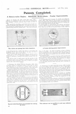
R. II. FOWLER and H. LIVESEY, No. 29,764, dated 24th December, 1913.—The object of this invention is to provide an improved construction which permits relative movement in the vertical direction between the driving wheel of a traction engine and the shaft driven by this wheel. A driving-plate is used between the driving and driven members, and it engages each of them by a series of projecthins, these on one side of the plate being at right eagles to those on the other. In order to provide as large a driving surface as possible, each face of the plate has across it as many parallel grocrms as is compatible with a suitable width of !4yt;ove. The plate is of annular form and surrounds the hub of the driving wheel. The driven shaft is mounted in bearings which permit it to move vertically within the hub of the driving wheel, and it has keyed on it a flange provided with projections to engage the corresponding ones on the driving plate.
The slotted plate maintains driving connection between the two at all times, however much they may move relatively to one another.
W. BOTTOMLEY, No. 9414, dated 9th October, 1913.—Iu this silencer the baffling effect is produced by wire, or steel shavings, through which the gases have to pass, and the special feature is that the size of the shavings is graduated, the exhaust gases meeting first the coarser material and then successively finer material so that the baffling effect is continued until the gases pass out of the silencer. The filling for the silencer may be supplied in cartridge packets, and it is held in place between perforated plates in the interior of the casing. These plates are positioned by means of adjustable setscrews SO that the compression of the shavings can be altered. Should the filling become affected or choked by the products of combustion it can easily be removed, cleaned and replaced. By adjusting the perforated plates the required baffling effect can be obtained under any condition.