 1
1 2
2 3
3 4
4 5
5 6
6 7
7 8
8 9
9 10
10 11
11 12
12 13
13 14
14 15
15 16
16 17
17 18
18 19
19 20
20 21
21 22
22 23
23 24
24 25
25 26
26 27
27 28
28 29
29 30
30 31
31 32
32 33
33 34
34 35
35 36
36 37
37 38
38 39
39 40
40 41
41 42
42 43
43 44
44 45
45 46
46 47
47 48
48 49
49 50
50 51
51 52
52 53
53 54
54 55
55 56
56 57
57 58
58 59
59 60
60 61
61 62
62 63
63 64
64 65
65 66
66 67
67 68
68 69
69 70
70 71
71 72
72 73
73 74
74 75
75 76
76 77
77 78
78 79
79 80
80 81
81 82
82 83
83 84
84 85
85 86
86 87
87 88
88 89
89 90
90 91
91 92
92 93
93 94
94 95
95 96
96 97
97 98
98 99
99 100
100 101
101 102
102 103
103 104
104 105
105 106
106 107
107 108
108 109
109 110
110 111
111 112
112 113
113 114
114 115
115 116
116 117
117 118
118 119
119 120
120 121
121 122
122 123
123 124
124 125
125 126
126 127
127 128
128 129
129 130
130 131
131 132
132 133
133 134
134 135
135 136
136 137
137 138
138 139
139 140
140 141
141 142
142 143
143 144
144 145
145 146
146 147
147 148
148 149
149 150
150 151
151 152
152 153
153 154
154 155
155 156
156 157
157 158
158 159
159 160
160 161
161 162
162 163
163 164
164 165
165 166
166 167
167 168
168 169
169 170
170 171
171 172
172 Powered Steering Gear
Page 126
If you've noticed an error in this article please click here to report it so we can fix it.
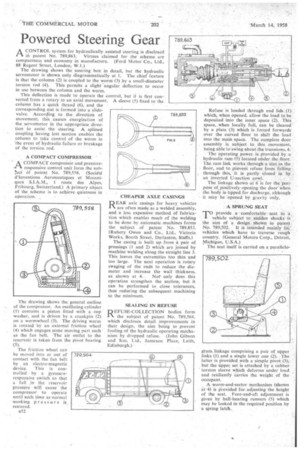
ACONTROL system for hydraulically assisted steering is disclosed in patent No. 789,863. Virtues claimed for the scheme are compactness and economy in manufacture. (Ford Motor Co., Ltd., 88 Regent Street, London, WA.)
The drawing shows the steering box in detail, but the hydraulic servomotor is shown only diagrammatically at I. The chief feature is that the column (2) is coupled to the worm (3) by a small-diameter torsion rod (4). This permits a slight angular deflection to occur in use between the column and the worm.
A COMPACT COMPRESSOR • A COMPACT compreisar and pressure-PA responsive control unit form the sub cf patent No. 789,558. (Societe d'Inventions Aeronautiques et Mecaniques SIAM., 1 route des Aloes, Fribourg, Switzerland.) A' primary object of the scheme is to achieve quietness in operation.
The drawing shows the general outline of the compressor. An oscillating cylinder (1) contains a piston fitted with a cup washer, and is driven by a crankpin (2) on a wormwheet (3). The driving worm is rotated by an external friction wheel (4) which engages some moving part such as the fan belt. The air outlet to the reservoir is taken from the pivot bearing (5).
The friction wheel can be moved into or out of contact with the fan belt by an electro-magnetic device. This is controlled by a pressureresponsive switch so that a fall in the reservoir pressure wilt cause the compressor to operate until such time as normal working pressure is restored.
B52 CHEAPER AXLE CASINGS
D EAR axle casings for heavy vehicles
are often made as a welded assembly, and a less expensive method of fabrication which enables much of the welding to be done by automatic machines forms the subject . of patent Na.. 789,853. (Rubery Owen and Co., Ltd., Victoria Works, Booth Street, Darlaston, Staffs.) The easing is built up from a pair of pressings (1 and 2) which are joined by machine wekling along the straight line 3. This leaves the extremities too thin and too large. The next operation is rotary swaging of the ends to reduce the diameter and increase the wall thickness,
as shown at 4. Not only does this operation strengthen the section, but it can he performed to close tolerances, thus reducing the subsequent machining to the minimum.
SEALING IN REFUSE
REFUSE-COLLECTION bodies form the subject of patent No. 789,564, which discloses detail improvements in their design, the aim being to prevent fouling of the hydraulic operating mechanism by dropped refuse. (John Gibson and Son, Ltd., Jameson Place, Leith, Edinburgh.) Refuse is loaded through end lids .(1) which, when opened, allow the load to be deposited into the inner space (2). This space, when locally full, can be cleared by a plate, (3) which is forced forwards over the curved floor to shift the load into the main space. The complete door assembly is subject to this movement, being able to swing about the trunnions, 4.
The operating power is provided by a hydraulic ram (5) located under the floor. The ram link works through a slot in the floor, and to prevent refuse from falling through this, it is partly, closed in. hy an inverted U-section cowl.
The linkage shown at 6 is for the purpose of,positively opening the door when the body is tipped for discharge, although it may be opened by gravity only.
A SPRUNG SEAT
TO provide acomfortable' seat in a vehicle subject to sudden shocks is the aim of a design shown in patent . No. 789,502. It is intended mainly fol vehicles which have to traverse rough country. (General Motors Corp., Detroit, Michigan, U.S.A.)
The seat itself is carried on a parallelo gram linkage comprising a pair of upper links (1) and a single lower one (2). The latter is provided with a simple pivot (3), but the upper set is attached by a rubber torsion sleeve which deforms under load and resiliently carries the weight of the occupant.
A worm-and-sector mechanism (shown at 4) is provided for adjusting the height of the seat. Fore-and-aft adjustment is given by ball-bearing runners (5) which may be locked in the required position by a spring latch.