


Converting from Four
Page 62
If you've noticed an error in this article please click here to report it so we can fix it.
to Six Wheels
A Raumi of Recently Published Patent Specifications
T0 convert a two-wheeled axle to one having four driving wheels is the aim of a unit shown in patent No. 582,455, by S. Opperman and Ganwick Estates, Ltd., Abford House, Wilton Road, London, S.W.!. The scheme calls for little or no modification of the vehicle to which it is fitted.
The standard hub is removed, and in its place is fitted a special hub (1) which is extended to carry a pair of chain sprockets (2): Also pivoted on the hub is the centre of a rocking beam (3) which carries, on suitable bearings, a road wheel at each end. Each wheel is provided with a Sprocket, as at 4, to receive the driving chain from the hub. A ratio reduction is incorporated in the drive, a suitable value being 2 to 1 or more.
No mention is made of brakes; it is presumed that the existing ones on the axle would continue to be used.
A SIMPLE RUBBER-MOUNTED UNIVERSAL JOINT
PATENT No. 583,296, comes from the Birmingham Small Arms Co„ Ltd., and I. Fletcher, both of Artnoury Road, Small Heath, Birmingham. The subject is a flexiblecoupling for use in the transmission system of a vehicle. The joint resembles, geometrically, the well-known Hooke's joint, but it employs balls in rubber sockets instead of pivot pins.
The drawing shows sufficient of the coupling to illustrate its action. The basic unit is a twoarmed member II) fitted with spherical ends (2) enclosed in shaped rubber blocks (3). The set of four blocks is held in an annular casing (4) which controls the concentricity of the whole. This easing is made in halves and united by fot.r bolts.
The specification states that the rubber is not bonded in any way, but does not mention whether thc rubber is used as an ordinary bearing material or whether it flexes without relative Mot ion.
A PISTON THAT WILL NOT "SLAP"
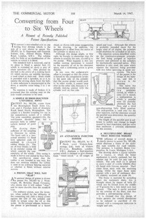
AN unusual design of piston is shown in patent No. 582,465 by I. Wainwright, 40, Berkeley Road, Coventry, who claims that it will reduce "slap," and be more durable than the standard type. The ordinary piston, says the inventor, when rocked by the obliquity of the connecting rod, rubs a sharp corner against the side of the cylinder and tends to scrape away the oil at this point. In the present scheme, however, the piston is pre-formed to a barrel
.
shape, as shown with some exaggeration in the drawing.' In addition, the gudgeon-pin is offset from the centre of the cylinder as shown at 1. Although this design might, at first sight, be thought to encourage ;lap, the reverse is actually the case, according to the patent. What .happens is that any sudden rocking movement is resisted by the quantity of oil in the clearance space, and a cushioning action is given thereby. In any case, the gudgeon-pin offset is arranged so that the piston is forced by the compression stroke to the same side of the cylinder that the power stroke would push it; in other words, it cannot snap over to the other side, because it is already making contact with the cylinder wall on that side. speed and load. Although the scheme is probably intended more for the larger sizes of oil engine, the principle could doubtless be extended to all sizes.
The injection system described works on the continuons-pressure principle, the fuel being pumped at injection pressure and admitted to the cylinders by mechanically operated valves. -Pilot injection is also used, the cams which operate the injectors being provided with two lobes operating in quick sueCession. The basis of the patent is the design of the injector, and this is shown in the drawing.
. The valve has three distinct work in g positions; closed, in which a cone (1) is seated, a mid-position in which a parallel nose (2) partially obstructs the fuel flow, and a third non-obstructing fully lifted position. The mid-position is used only for the pilot injection, and the clearance around the parallel nose determines the quantity of fuel passed.
The length of the parallel part is sufficient to nullify any change in length caused by heat expansion, and the valve thus maintains a constant adjustment on this account.
A MULTIPLE-DISC BRAKE THAT REDUCES WEIGHT
THE influence of aircraft design is clearly shown in patent N. 583,108, which discloses a brake of the multidisc type suitable for road vehicles. The patentee is Lambert Brake Corporation, St. Louis, Michigan, U.S.A. The drawing shows a layout suitable for a tractor, in which the brake mechanism is totally enclosed, but the scheme can be used for any type of vehicle. The axle shaft (1) is spline(' to carry a pair of axially slidable discs
(2) faced with friction material. The!! outer faces mate • with the enclosing easing, whilst the inner faces make contact with a pair of stationary discs. (3) slidably mounted on studs (4). The brake is operated by spreading apart the stationary discs; this is brought about by means of balls (5) which can be forced from the middle of V-grooves by a thin metal cam (not shown). The earn is partly powered by the rotation of the discs, and thus provides a self-energizing action.
It is claimed that this design of brake permits the overall dimensions to be reduced to one-third of the normal, with a consequent reduction in weight and cost.