


A Clutch-operated
Page 34
Page 35
If you've noticed an error in this article please click here to report it so we can fix it.
Steering Gear
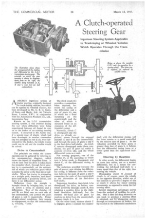
AHIGHLY ingenious system of tractor steering, originally designed for track-laying vehicles, but which can be applied to wheeled tractors, has been developed by Mr. G. R. G. Gates, of Gates and Hardy, Ltd., 66, Victoria Street, London, S.W.1. in conjunction with the Automotive Products Co., Ltd., Leamington Spa.
Known as the L.G.1 transmission steering system, it was evolved during the war when difficulties were being experienced because oil found its way on to the brakes of an existing steering system. It occurred to Mr. Gates that, if a special type of clutch, which had been developed in another connection and was designed to run in oil, were substituted for the brakes, the whole system could run in oil and the trouble would be solved.
Drive to Countershaft The principle on which the system operates can be gathered by referring to the accompanying diagram, which shows the layout in simplified form. It will be seen that the drive is taken from the propeller shaft, through bevel gearing, to a countershaft, on the extremities of which are reduction gears which transmit the drive to the final-drive halfshafts. When the tractor is proceeding on a straight path, therefore, each finaldrive half-shaft is positively driven, and there is no differential action.
Deflection from the straight is brought about by bringing into, or out of, action a series of clutches and a differential. Two of the clutches (A and B) are flaw one on each side of the countershaft, and control the pairs of gears a and b respectively. Under straight-ahead conditions, they remain in engagement, so that the countershaft is, virtually, "solid." The third clutch (C) provides a connection, when required, between the casing of the differential and a pair of gears (c), one . of which has a used mounting on the countershaft and the other of which is mounted freely on an extension of the differential casing.
Normally, clutch C is disengaged and the drive, as already explained, passes through the engaged clutches A and B on the countershaft, and through the pairs of gears a and b to the final-drive half-shafts. As clutch C remains disengaged under these conditions, the pair of gears (c) which it controls revolves idly, and the whole differential turns as a unit.
For steering purposes, one of the clutches (A or It), according to which turn is being made, is disengaged, and clutch C, on the differential casing. is engaged.
The reduction provided between the pair of gears c, now driving the differential casing, is different from the reduction between the pairs of gears a and b connecting the ends of the countershaft to the extremities of the final-drive half-shafts.
Supposing, therefore, that clutch A be disengaged, the drive, as before, continues positively through clutch B, thus retaining a positive .drive to the righthand final-drive half-shaft, but the extreme left-hand pair of gears (a) receives no drive from the countershaft, because clutch A is free.
On the other hand, because clutch C is engaged, gears c connect the counter
shaft with the differential casing, and the latter rotates at a speed controlled by the relative sizes of gears e. As the reduction provided by these gears is greater than that of gears b, it follows that the differential casing turns at a lower speed than the right-hand halfshaft.
Steering by Reaction
In other words, the differential begins to come into action, not as a normal differential, but as a means for controlling the left-hand half-shaft to a lower speed than that of the right, thus steering the vehicle.
Disengaging clutch B ,instead of clutch A, of course, steers the vehicle in the opposite direction, whilst use of the controls to provide a degree of slip at clutch C allows for minor steering movements, as opposed to using the full turning effect.
Several important advantages accrue from this method of tackling the problem. One is that the drag necessary on one track to produce a steering effect is obtained, not by dissipating energy through an arrangements of brakes, but by reaction in the differential mechanism
against the other track. In other words, the system is regenerative and the total tractive effort required for cornering is the same as on the straight.
The second point is that there is no geared-up effect on the outer track, as occurs with a simple braked differential; instead, the engine maintains a constant speed, and, as the speed of the centre line of the vehicle is lower, the actual power required when cornering is slightly less and liability to stalling on a turn is eliminated.
Finally, as already indicated, there is a positive connection between the two tracks when the vehicle is travelling straight, and track slip on boggy ground through differential action cannot take place.
It was men:ioned at the outset that this steering is also suitable for wheeled tractors. For this application a front castor wheel would take the place of the normal steered wheels, and steering would be carried out by means of the driving wheels through the medium of the L.G.I system.
We have tried the scheme as applied to a smalltraekalaying tractor, and we found that it–not only fulfilled all the claims of its designer in the matter of easy handling, hut it impressed us as providing outstandingly delicate control.