


Patents Completed.
Page 24
If you've noticed an error in this article please click here to report it so we can fix it.
Complete specifications of the following patents will be sent to any address in the United Kingd,m upon receipt of eightpence per copy at the Sale Branch, Patent Office, Holborn, W.C.
A Detachable Wheel.
C. H. Crawley and A. Shortland.— No. 24,059, dated 18th October, 19i0— Cognate Applications Nos. 26,018;10 and 5043/11.—The wheel described in this specification comprises a permanent clutch-part carried on the axle and which is not removed with the wheel; a removable clutch-part fixed on the inner end of the hub of the wheel and removed with it; a toothed plate by which the two clutch-parts are locked together and means for imparting locking movement to the various members. The permanent clutch-part. comprises a disc having flanged jaws formed on it, equally spaced around the hub. The removable clutchmember is formed as a disc on the end of a sleeve, having jaws which engage with those on the permanent clutch-part. It is externally screwed and carries a sleeve which also engages the same jaws. The operation of attaching the wheel is as follows. It is placed in position on the vehicle-axle, so that the jaws of the removable clutch-part fit between the jaws of the permanent clutch-part. A partial turn is given to the removable clutchpart which is conveniently formed hexag-onally for this purpose, and the jriws of the removable clutch-part are thereby brought under the flanges of the jaws of the permanent. clutch-part and locked thereto. A slight clearance is left to allow for the longitudinal movement of the parts due to the rotation on the threaded collar. A modification is also described and illustrated in this specification.
Hinged Flange Rim for Tires,
R. Brown and C. Pallash.—No. 16,149, dated 12th July, 1911.—This invention relates to wheels fitted with resilient tires and has for its object to provide means whereby such tires may be readily removed or applied to the rim. Ori a portion of the rim, preferably about
half, one of the beads is detached and secured by hinges to the remainder. A dependent flange of this hinged part lies against the felloe when it. is in position and is secured thereto by slotted washers hinged to the flange and engaging bolts passing through the felloe.
An Anti-skidding Device.
A. Bosshard.—No. 25,333 of 1911, dated under the International Convention, 24th November, 1910,—This specifi
cation describes an anti-skid device of the type in which a chain having transverse projections is situated between, and supported by, twin tires. The invention consists of an arrangement whereby the anti-skid projections are connected by flat links which lie in the space between the tires, and which are held in slots in the ends of the transverse members so that all the links are kept in line with one another. The intermediate links are provided with a series of holes for the pins by which they are secured to the transverse members, whereby the length of the chain can be varied as required.
Re-tiring without Hydraulic Press. E. W. Thomas.—No. 5069, dated 28th February, 1911.—This invention relates to wheels of the type in which the con
tinuity of the rim is interrupted by gaps, so that the size of the wheel can be increased or decreased, whereby a tirecarrying rim can be easily removed. The specification describes a cast-steel wheel suitable for use on a commercial-motor vehicle. The wheel comprises the ordinary rim united in the usual way by spokes to the hub ; a gap is left in the rim, however, to be occupied by an in sertion block, secured in place by bolts or other suitable fastening. When the insertion block is removed, the rim contracts. This wheel was illustrated in the " C.M." for 27th April last.
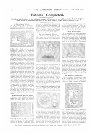
A New Splashguard.
J. R. Rowland.—No. 4238, dated 20th February, 1911.—The accompanying illustration shows a section of the rim of a motor-vehicle wheel which is provided on the left-hand side with a mudguard to prevent the side-splashing of mud which is so objectionable. The guard consists of a single round rim formed of a strip of sheet iron, aluminium or like metal, of a suitable width. One side of the rim is bent or curved to form a flange by which it is attached to the wheel in any convenient manner, while the other side of the rim is bent downwards, notfar enough to reach the road level but protruding; sufficiently to catch the major portion of the side splashing of mud.
An American Taximeter.
Marks Pittsburg Taximeter Co.—No. 28,161, dated 25th January, 1911.--The object of this invention is to provide a taximeter which is simple in construe
tion, compact and having all indicators, and registers easily accessible for inspection. The operation of the taximeter as a, whole is described in Specification No. 1953 of 1911, and the present invention consists in the fare-indicating and registering mechanism, having a plate carrying a housing removably secured thereto, a shaft mounted in the housing and the various registers all mounted oi. the same shaft independently operated.