


Patents Completed.
Page 56
If you've noticed an error in this article please click here to report it so we can fix it.
EXHAUST SIT. NCER.—Hotchkis.-No. 12,586, dated 30th May, 1906—The exhaust gases are subjected to the inductive action of ejectors in order to lessen
the back pressure in the cylinders. The silencer (A) is of cylindrical form, and divided into a number of compartments by partition plates (B, B), each carrying an expanding nozzle or flaring tube (C). The exhaust pipe is lead in, as shown at 1), and, in passing through the successive nozzles, tends to create a partial vacuum in the respective chambers, and finally discharges into the atmosphere at E.
GRADUALLY ACTING CLUTCH.— Compagnie Beige de Construction d'Automobiles Usines "Pipe," and Another.— No. 19,021, dated 25th August, 1906.— This clutch or,. coupling consists of an outer drum (1) lined with removable friction packing .(2), forming the outer member, and a shaft (5) carrying the inner member of the clutch. A triangular-shaped plate (3) is fixed to the shaft and is provided with a notch (11) to hold ne end (10) of a spiral steel strip (9) normally fitting freely in the outer drum. The other end of the spiral (16) is connected by an adjustable link (17) to a lever (15) fillcrurnmed on a pivot (14) which is fixed in a plate (12) of, approximately, annular form. This last is fixed to, and at a distance from, the triangular plate (3) by three bolts (13). The lever (15) is provided with a roller (18) and is actuated by an inclined slot (8) formed in a projection carried by a sliding sleeve (7) feathered on the shaft (5), the said sleeve being pressed by a spiral spring (not shown) on the shaft in such a direction as to turn the lever (15) as directed by the arrow, to hold the clutch in engagement.
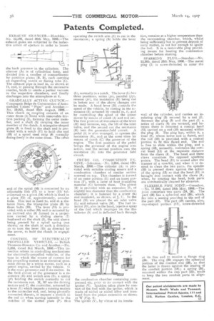
CONTROL OF ELECTRICALLY PROPELLED VEHICLES. — British Thomson-Houston Co. and Another.—No. 5,263, dated 3rd March, 1906.—This invention ielates to controlling mechanisms for electrically-propelled vehic:es, of the type in which the source of current for the propelling motors is an electrical generator driven by a prime mover, such as a petrol engine, carried by the vehicle. G is the main generator and E its exciter. In the field circuit of the generator is a resistance (R) and switch arm (S), a spring (pl) holding the switch normally to cut the resistance out. M, MI are the driving motors and C, the controller, actuated by a lever (1...) which imparts a turning motion to the controller rod, and, being pivotally connected thereto, it imparts a motioli to the rod (s) when moving laterally in the notches of the slotted plate (P), thus
operating the switch arm (S) to cut in the resistance; a spring (B) holds the lever
(L), normally in a notch. The lever (L) has three positions, series (p), parallel (pp), reverse (pr), the resistance (R) being cut in before any of the above changes can be made. A hand lever (H) controls the speed of the vehicle, by cutting in the rzsistance (R) actuated by cranks (n, ,t), and by controlling the speed of the prime mover by means of crank (k) and rod (m). The first position of movement of the lever (H) may increase, say, the lift of the inlet valve, and the second cut the resistance (R) into the generator-field circuit. A pedal Of is also arranged, to operate the resistance (11), and at the same time by means of crank (C) the governor of the engine. The first position of the pedal brings the governor of the engine into action, and the second position cuts the resistance (11) into the generator field circuit.
CRUDE OIL COMBUSTION ENGINE.—Johnston.—No. 5,954, dated 12th March, 1906.—The cylinder (A) is provided with suitable cooling means and a combustion chamber of similar section screwed on top. This chamber is formed of an outer portion (E) and an inner portion (17), with a layer of heat insulating material (G) between them. The piston (B) is provided with an extension (1), of slightly less diameter than the combustion chamber ; it is fastened by a screw (K) and insulated, as shown, at J, U. In the head (H) are placed the air inlet valve (L) and exhaust valve (M). The fuel injector (0), also in the head, injects a spray of the fuel which impinges on the distributor (S) and is deflected back through the combustion chamber containing corn. pressed air, prior to its contact with the igniter (V). Ignition takes place by contact of the fuel with the igniter, which is made of nickel or nickel alloy and insulated from the piston extension as shown at IV (Fig. 4).
The igniter (V), by virtue of its insula tion, remains at a higher temperature than the surrounding chamber, which, whilst being sufficiently hot to prevent deposit of tarry matter, is not hot enough to ignite the fuel. X is a removable plug providing means for heating the combustion chamber before starting.
SPARKING PLUG.—Streuber.—No. 12,305, dated 26th May, 1906.—The metal plug (I) is screw-threaded to enter the wall of the cylinder, and carries an insulating plug (3) secured by a nut (2). Between the plug (3) and the part (1) a series of claws (4) are secured, and between these is mounted a conical head (11) carried on a rod (10) mounted within the plug (3). The plug has, within it, a liner (8), whose lower end is Bared, and the rod (10) is provided with a conical portion to fit this flared end. The rod is free to slide within the plug, and a spring (13), normally, maintains the conical head. (11) at the requisite distance from the claws (4). The head and these claws constitute the opposed sparking points. The head (11) is scored after the manner of a rose-bit, and when it is desired to clean the two parts, the spindle (10) is pressed down against the action of the spring (13) so that the head (11) is brought into contact with the claws (4), when, by rotating the bead, both parts are automatically cleaned by abrasion.
FLEXIBLE PIPE JOINT.—Greenla,,v. —No. 11,680, dated 18th May, 1906.—The joint comprises two parts (18, 26). The part (26) has a spherical end (30), which fits into a seating provided in the end of the part (18). The part (18) carries, also, cup-shaped portion (17), screw-threaded
at its free end to receive a flange ring (29). The ring (29) engages the spherical portion of the conduit end (26), so that the latter 55 drawn against the seating of the conduit portion (18) ; a spring (34), mounted within the cup part (22), tends to keep the two conduit parts in alignment.