


MATTERS CONCERNING LATHES.
Page 27
If you've noticed an error in this article please click here to report it so we can fix it.
Suggestions by Our Driver and Mechanic Readers,
FREQuE NTTLY it is desirable to be able to turn up new piston rings for any particular vehicle in the workshop, and " H.A.B.," 'of Rotherham, describes a method which he adopts in this connection, for which this week's prize of 35s. is awarded.
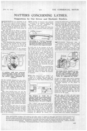
The first step is to obtain a casting from which the rings may be machined. One of the tips which " H.A.B." gives is to have four equally spaced lugs cast inside the "bush," in order that it may be bolted securely to the faceplate of the lathe to ensure accuracy and to reduce the risk of breakage both of rings and tools. .
When obtaining the casting it should be ordered long enough for the necessary number of rings to be turned off in addition to the allowances for the width of the parting tool.
One important point is the amount of spring which is given to a piston ring, and the method adopted by our correspondent is to measure the diameter at the bottom of the ring grooves of the piston, and then to bore out the casting from which the rings are cut 1-16 in. larger than the diameter of the groove. The outside of the casting is turned 1-16 in. larger than the cylinder bore.
The rings having been cut off the remaining part of the casting, which is bolted to the faceplate, is turned on the outside to the diameter of the grooves at the bottom. Two of the four holding-down bolts are removed and longer ones substituted. A plate of the same diameter as the turned casting is slipped over those bolts and tightened down, nipping a piston ring between the plate and the casting.
In this manner the ring is securely held and the finishing cut may be made when the gap has been closed, continuing the turning until the ring is some six-thousandth of an inch less than the bore of the cylinder.. THE cutting of internal and external keyways in an ordinary lathe forms the subject of the suggestion of
H.F.R.," of London; S.E.13.
In the case of a shaft, two Mies are drilled, of the required width and depth,
at each end of the keyway to be cut. The shaft is next mounted in the lathe, one end in the chuck and the other end in the back centre. A parting tool or an old flat file is taken and ground to the exact width of the key. The tool is secured on its side in the ordinary manner in the tool-rest, taking care to see that the centre of the cutting edge coincides with the lathe centre.
The shaft is firmly held by means of the engagement of the back gear and the cut is made by traversing the toolrest backwards and forwards through the required distance.
In a similar manner an internal keyway may be cut by gripping the part in the chuck, and traversing the tool-rest backwards and forwards with the tool inside the orifice in which the keyway is required.
THE first suggestion of "FR.," of Bath, is a safety lock nut for the spindle of a grinding wheel which is substituted for the usual hexagon lock nut.
The " blind" nut is turned out of a piece of round steel drilled at its cloSed end and tapped to fit on to the spindle. The depth of the round nut should be such that the end of the spindle just comes flush with the outside of the nut. Rotation for tightening and loosening purposes is effected by means of a tominy-bar fitted into a small hole in the exterior of the nut. There are no sharp edges to catch the sleeves or clothes ot operators, and danger is thus reduced.
In the absence of proper creaked clamps, F.H." advocates the use of a simple low-clamping device. A packing block of suitable height is taken and a piece of bar steel bolted above it. The bar has a hole through the other end, which permits of a T clamp being fixed through it, which, when pulled down, grips the work at one end and rests upon a packing strip at the other. In this way there is no nut above the clamp.
MECHANICS frequently find it necessary to cool the work in a, lathe while turning, and the use of a Movable suds pump is desirable. " R.H.," of Trowbridge, suggests using an empty half-gallon oil tin as the container, this being placed on a shelf above the lathe.
A piece of copper tube and a suitable length of rubber piping provide the means of carrying the suds to the point at which delivery of the liquid is required.
The control of the direction and speed of flow is obtained by the use of a tap held in a piece of strip iron bolted under one of the tool-post studs. By this means the tap travels with the tool and guides the suds to where they are required on to the work.
IN the case of some old and worn
lathes, difficulty is experienced in parting off a heavy piece of steel owing to the mandrel lifting and possibly breaking the tool. " P.H.," of Holloway, sug
gests the following tip. By crossing the belt and thus running the lathe backwards, the tool being inverted, a higher speed can be used without the risk above mentioned. A heavier cut in turning may also, be taken by utilizing the same scheme, according to our correspondent. It appears desirable to use this tip as an emergency expedient rather than as a routine procedure.