


A Power-actuated Gear Change
Page 80
If you've noticed an error in this article please click here to report it so we can fix it.
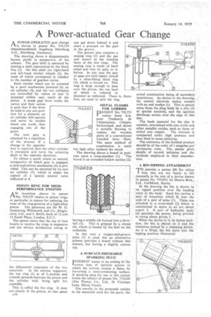
A POWER-OPERATED gear change /A is shown in patent No. 719,559 (Maschinenfabrik Augsburg Nurnberg A.G., Niirnberg, Germany).
The drawing shows 'a diagrammatic layout, partly in perspective, of the scheme. The gear shift is operated by turning a shaft represented by the black line (1). On this shaft are right-hand and left-hand ratchet wheels (2), the teeth of which correspond in number to the number of gearbox ratios.
Each ratchet wheel can be actuated by a pawl mechanism powered by an air cylinder (Y), and the two cylinders are controlled by valves (4 and 5) mounted within easy reach of the driver. A mock gear lever works the valves and their action is such that if the lever be held in any one position for a moment, an air cylinder will operate and move its ratchet wheel one tooth, thus engaging one of the gears.
The next gear is obtained by a repetition of the process. If a change in the opposite way is required, then the other cylinder is energized and turns the actuating shaft in the opposite direction.
To obtain a quick return to neutral, irrespective of which gear is engaged, a rack-and-pinion mechanism (6) is provided. This can be operated by its own air cylinder (7), which is under the control of a special neutral valve inaicated at 8.
PISTON RING FOR HIGHPERFORMANCE ENGINES AN invention shown in patent No. 719,537 relates to piston rings, in particular to means for reducing the wear of the ring-grooves of a light-alloy piston. The patentees are Sir W. G. Armstrong Whitworth and Co. (Engineers), Ltd., and J. Smith, both of 12 and 13 South Place, London, E.C.2.
The patent states that the use of iron inserts to receive the rings is expensive and not always satisfactory owing to the differential expansion of the two materials. In the scheme suggested, the top ring (1) is of L-section and extends upwards between the piston and the cylinder wall, being split for assembly.
This is called the fire ring. It does not closely fit the piston, so that gases can get down behind it and exert a pressure on the part in the groove.
The groove also contains a seating ring (2) and the gas seal occurs at the meeting faces of the to rings. The seating ring is made of hard metal and may be split, or in halves. In any case the gap or gaps are held tightly closed • by a close-fitting third ring (3), which is forced on. This ring is large enough to pass over the piston, the top land of which is reduced in diameter as indicated. There is, fore, no need to split the ring.
METAL FLOORS FOR LORRIES
PATENT No. 719,751 comes from S.A. pour !Industrie de l'Aluminium, Chippis, Switzerland, and shows a metallic flooring to replace the wooden parts of a conventional boarded lorry • floor. The same method of construction is used, but light alloy replaces the wood.
The drawing shows a board in position upon a cross-member (I). The board is an extruded hollow section (2), having a middle rib formed into a dovetail (3). This is gripped by a clamp (4), which is loaded by the bolt on the underside.
In this case a tongue-and-groove joint (5) is used, but an alternative scheme provides a board without this feature, but having a slightly convex top.
A SURFACE-DISCHARGE SPARKING PLUG INTEREST seems to be arising in the 1 newer type of ignition system in which the current creates a flame by traversing a semi-conducting surface. A sparking plug for use in this system forms the subject of patent No. 719,628 (The Plessey Co„ Ltd., 56 Vicarage Lane, Ilford, Essex).
The novelty in the proposals resides in the materials used for the parts, the actual construction being of secondary importance. As shown in the drawing, the central electrode makes contact with an end washer (I). This is spaced away from the plug body by a disc (2) of special material, and the ignition discharge occurs over the edge of this disc.
The basic material for the disc is ceramic, intermixed with zinc oxide and other metallic oxides, such as those of nickel and copper. The mixture is compacted under high pressure and then fired to cause sintering.
The resistance of the finished product should be of the order taf I megohrn per centimetre cube. The patent gives details of several mixtures and the methods employed in their manufacture.
A BIN-TIPPING ATTACHMENT 710 provide a power lift for refuse bins that are too heaVy to lift manually is the aim of a device shown in patent No. 719,825, by Dennis Bros, Ltd., Guildford, Surrey.
In the drawing the bin is shown in its tipped position over the loading entry to the body. Each bin carries a pair of 'trunnions which fit into the ends of a pair of arms (1). These are attached to 5. cross-shaft (2) which is constrained to move in an arc about centre 3. A pair of hydraulic jacks (4) provides the power, being pivoted to swing about pivots 5.
When the device is in its lowest position, the bin is placed on it and the trunnions locked by a clamping device. As it is lifted, the bin turns into the tipping position illustrated.