


Patents Completed.
Page 22
If you've noticed an error in this article please click here to report it so we can fix it.
Complete specifications of the following patents will be sent to any address in the United Kingdom upon receipt of eightpence per copy at Sales Branch, Patent Office, Holborn, W.C.
EsILIFINT WHEEL—Her-ton and Another.—No. 3,548, dated 17th February, 1908.—This invention relates to resilient wheels of the type in which the hub is suspended by a number of radially -disposed spiral springs. The rim of the wheel has an inwardly-extendieg central flange to which one end of each spiral spring is secured, its other end being secured to the hub. Also fast on the hub are two convex discs which abut the central flange of the rim. The present improvement consists in the provision of twe iudia-rubber rings tA) -that are secured by their outer edges to the rim, and by their inner edges to the convex discs. These rings, -together with the spiral springs, take the load and transmit the drive to the rim, or the rings may be sufficiently strong to allow the elimination of the spiral springs. A number of bolts passing through the dished plates and central flange aforesaid stiffen the structure and counteract any tendency to a lateral shifting of -the rim portion independent of the heb of the wheel.
SPARE WHEEL ATTACHMENT.— Dennis.—No. 5,117, dated 6th March, 1908.—The rim (a) of the spare wheel is provided with a conical flange le), which is adapted to engage with a similarly coned portion of the rim (e: of the vehicle wheel, thus ensuring the spare wheel running truly with the vehicle wheel. A
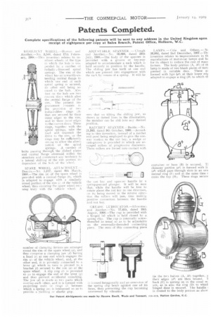
number of clamping devices are arranged round the rim of the spare wheel (a), and they comprise a clamping jaw (d) having a head (Cl at one end which engages the rim (c) of the vehicle wheel, and, at the other end, it is pivotally connected to a lever 4) which in turn is pivoted to a bracket (1) secured to the rim (a) of the spare wheel. A slip ring lei is provided so as to engage the end of the lever (g) and thus prevent accidental unlocking. The j;w tel) is made in twe parts which oterlap each other, and it is formed with projecting .ends or• rings cf; between which a spring m is interposed so as to provide a Yielding or elastic grip. ADJUSTABLE ePANNER. — Clough and Another.--No. 16,090, dated 29th July, 1908.-1'he body of the spanner is provided with a groove or key-way adapted to accommodate a rack which is held securely in position by the handle. '1'he sliding jaw has teeth at one end which are pressed into engagement with the rack by means of a spring. It will be
seen that on tilting the sliding jaw, as show:i in dotted lines in the illustration, the member can be slid into any desired position.
RATCIIET SPANNER.—Budde.—No. 21,343, dated 9th October, 1908.—According to this invention, instead of a ratchet and pawl being employed to give the oneway motion to the Out key, a wedge or cam-groove is provided in which are arranged rollers of progressive diameters. These rollers are force into contact with
the nut key and spanner handle by a spring-pressed plunger. It will he seen that, while the handle will be free to rotate about the nut key in one direction, on its being moved in the reverse direction the roller; will jam, faus making positive connection between the handle and nut key.
GREASE LUBRICATOR—Silverman and Another.—No. 17,455, dated 19th August, 1908.—The cup is provided with a binged lid which is held closed be a spring clip. The cup is internally screwthreaded as usual se as to be adjustable on the externally-threaded connecting piece. The stem Of this connecting piece Is :Orme(' hexagonally and an extension of the spring clip bears against one of its faces, thus preventing the cup becoming unscrewed by vibration.
LAMPS. —Cole and Others.— Nt 26,002, dated 2nd December, 1907.—Thi invention relates to improvements in th manufacture of motor-car lamps and ha for its object to reduce the cost of mart facture. The body portion (A, Ali of th lamp is made of two blank pieces of met; pressed in suitable dies. These at formed with lips (44) at their lower edg adapted to engage a ring 011 to which th container or base (B) is secured. T1 chimney portion (a6) is formed with Ii (a6) which pass through slots in an orn mental ring (F) and at the same time s cures the top (Hi. These rings secure tie the twe halves (A, Al) together, a their edges (a6) are then brazed. 'I hack (C) is sprung on in the usual ne Der, as is also the ring (D) to whick hinged door is secured. 1 he handle i is riveted to the body pat eon as show