


Steering by Clutches
Page 80
If you've noticed an error in this article please click here to report it so we can fix it.
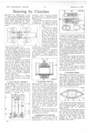
PATE N T No. 788,800 refers to large machines such as bulldozers, tractors and others which must exert great power and are capable of travelling on roads. The scheme shown deals with the general layout of the transmission on a fourwheel-drive machine. (N. Straussler, 5 1788.800 t ;6)
Clarges Street, London, W.1.) The drawing show§ a plan of a fourwheel-drive vehicle. The wheels in this case arc not sprung, although they may be. The axle assembly is pivoted about trunnions (1) which permit up to 15° of deflection. The engine (2) drives through a clutch and the two gearboxes in series, giving eight speeds in all.
The drive is divided by a first bevelbox (3), this contains four meshing bevels, and by selective clutching of the front or rear "one, a reverse canbe obtained for all speeds. The drive is taken by cross-shafts (4) to outer bevel boxes (5) whence the wheels are driven. The drive to each wheel includes a clutch (6) which is preferably electrically operated, and by selective engagement steering is performed.
Each wheel contains an epicyclic reduction gear of about 51 to 1 so that the axle shafts (7) can be small highspeed members.
A DUAL BRAKE ASSEMBLY
rAA BRAKING scheme shown in patent No. 788,586 is intended for large vehicles for which one set of brakes is insufficient. The proposed layout comprises a common drum and two pairs of brake shoes with their associated
mechanism, power operated, preferably by compressed air. (Deutsche PerrotBremse G.m.b.H., Mannheim-Friedriehsfelt!, Germany.) The back-plate is between the two sets as shown at I. The shoes are expanded by dual-piston air cylinders .(2 and 3), one on each side of the plate. _ Diametrically opposite is a pair of floating adjusters which separate the other ends of the shOes. Each adjuster.. is
... threaded rightand lefthand, and is moved by turning a nut made in the form of a wormWbeel Separate worms (5 and 6) mesh with these. and their coaxial. •spindles arc 'brought out to a point (7)
at which they can be individually adjusted by turning the squared -ends. ;
The expander cylinders are worked in unison, being charged via .a single inlet "(8) and connected by a -passage (9) to the backplate. A rubber scaling ring. at this point is one of the subjects of the patent.
A COMPOSITE BIG-END /X N assembly shown in patent No.
.rt 788,692 is a composite big-end bearing for use with two connecting rods, such as those of horizontally opposed or V-type engines. (Maybach-Motorenbau Friedrichshafen, Germany.) The two rods (1 and 2) surround a split bearing sleeve (I) made of high-strength bronze, whilst the centre rod has its own split bearing (4) running on the larger one. The chief point of the patent is the various surface treatments used. The main bronze bearing is surfaced inside and out with a layer of lead 0.02 mm. thick. The Outer bearing (4) is made of steel and is faced internally with chromium, or may be provided with a nitrided bore.
The high-strength bronze used for the large bearing is chosen to be suitable for running on in an emergency if the lead layer should be removed.
A RESPONSIVE GOVERNOR A CCORDINO to patent No. 788,546, I-1 accuracy in speed control of the injection Pump of a road vehicle is not
so important as rapidity of response, and it shows a governor designed with this aim in view. (G. Green and G. Fox,. 100 Wells Road, Malvern, Worcs.) The governor is hydraulically operated, and the drawing Shows a diagrammatic layout. An engine-driven' pump delivers liquid at a rate responsive to engine speed, and feeds a cylinder (1) provided with a spring-loaded _piston coupled to the injection putup control. This simple arrangement does not, however, give the most favourable speed/pressure ratio, and so a modifying by-pass is included in the liquid circuit.
This comprises a spring-loaded plunger (2) which, when opened by pressure, allows liquid to pass the plunger and reach an annuli's (3). From here it flows through a bore (4) controlled by a tapered valve. The fluid finally returns to the supply via the pipe (5): The profile of the tapered valve is important, by "suitable choice of outline the control curve can be made to have any desired characteristics.
A TRACKED WHEEL
TO enable a road wheel to be used as a self-laying track is the object of a scheme shown in patent No. 788,788. The system haS been covered by an earlier patent numbered 553,905; but the new design incorporates an improved means of keeping the tracks on the wheel. (E. Clifford and H. Leibrecht, 17 Holly Mount, London, N.W.3.)
The vehicle axle carries a sprocket (1) which has two sets of teeth. The tracks (2) arc channel-sectioned, the channel being provided with an upstanding central rib (3).
Pivots (4) pass through all three ribs and carry rollers to form a chain-like construction. On some of the rollers are pulleys (5), and around .these pass inextensible cables (6). These maintain the track members in close contact with the sprockets, but in no way impede the flexibility of the system.