


New Design of Farm Tractor
Page 54
If you've noticed an error in this article please click here to report it so we can fix it.
ACCORDING to patent No. 582,351, agricultural tractors fall into two classes—the full-size heavy machine and the ultra-light two-wheeled outfit. It is. further stated that there is a need for an intermediate type, and the patent describes such a machine. The patentee is A. Bean, "Half-Acres," Welton,
Brough, East Yorkshire.
One of the disadvantages of the fullsize machine is that the driver's view of the ground is obstructed so that he cannot closely follow crop rows, and the present machine is designed with a view to good visibility in this respect.
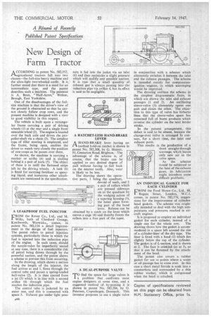
The vehicle is built upon a rectangular frame carrying a pair of driving wheels (1) at the rear and a single front steerable wheel (2). The engine is located over the back axle and drives the propeller-shaft via a chain (3). The simplest type of tiller steering is employed, and the frame, being open, enables the driver to watch very closely the position of row-crops as he passes over them.
As shown, the machine is carrying a marker or scribe (4) and is trailing behind it a pair of tools (5). The object of these is to retill the flattened strips left by the driving wheels. A tank (6) is fitted for carrying fertilizer or spraying liquid, and numerous other attachments are mentioned in the specification.
A LEAKPROOF FUEL INJECTOR
F"" the Rover Co., Ltd., and M. Wilks, both of Chesford Grange, Kenilworth, Warwicks., comes, in patent No. 582,116 a detail improvement in the design of fuel injectors. The patent refers to petrol injection systems, particularly those in which the fuel is injected into the induction pipe
of the engine. In such cases, should the nozzle-valve be imperfectly seated at any time, there is a considerable risk of petrol being drawn through by the powerful suction, and the patent shows a scheme to prevent this from occurring.
In the drawing, which shows a section along the length of the injector, the fuel arrives at end 1, flows through the central tube and passes a spring-loaded ball-valve (2). It is then ejected from a jet (3) which is in line with a second orifice (4) through which the fuel reaches the induction pipe.
The central tube is jacketed by an outer one, and this is connected with space 5. Exhaust gas under light pres
sure is fed into the jacket via an inlet (6) and thus maintains a slight pressure which will nullify any possible suction. It is true that a small quantity of exhaust gas is always passing into" the induction pipe via orifice 4, but its effect is said to be negligible.
A RATCHET-LESS HAND-BRAKE LEVER
A HAND-BRAKE lever having no IA toothed hold-on ratchet is shown in patent No. 582,308, by G. Hunter, 91, Centurion Road, Brighton. The advantage of the scheme is, of course, that the brake can be applied to any desired degree of pull without having to fall back on the nearest tooth. Also, wear is likely to be less.
The drawing shows the operative parts, 1 being the quadrant, devoid of teeth, and 2 a pair of rollers which Are pressed sideways on to the quadrant by the wedging action of a tapering housing (3), the latter piece forming part of the hand lever. Release can be obtained by a catch on the lever which moves a cage (4) and thereby forces the rollers into a free part of the taper.
A DUAL-PURPOSE VALVE
Prfind the space for large valves is a). problem that confronts most engine designers at some time, and a suggested method of by-passing it is shown in patent No. 582,204, by 0. Petersen, Copenhagen, Denmark. This inventor proposes to use a single valve
in conjunction with a selector which alternately switches it between the inlet and the exhaust passages. The scheme is intended mainly for compressionignition engines, in which scavenging would be improved.
The drawing outlines the scheme in the simplest diagrammatic form, in which are shown the inlet and exhaust passages (I and 2). An oscillating sleeve-valve (3) alternately opens one port and closes the other. The objection to this type of valve has hitherto lieen that the sleeve-valve space has remained full of burnt products which re-enter the cylinder on the next intake stroke.
In the present arrangement, this defect is said to be absent, because the change-over valve is arranged to connect, for a short time, the inlet and exhaust ports.
This results in the production of a short straight-through scavenge, which leaves only new air in the 'salve space.
As the selector would be subjected to the heat of the exhaust gases, its lubrication might introduce some difficult problems.
AN INDIVIDUAL GASKET FOR EACH CYLINDER
CROM the Ford Motor Co., Ltd., 88,
Regent Street, London, W.C.1, comes, in patent No. 582,376, suggestions for the improvement of cylindeahead gaskets. The scheme was originally intended to deal with the high temperatures and pressures reached in aircraft engines.
It is proposed to employ an individual gasket for each cylinder, instead of a single one for the whole row. The drawing shows how the gasket is accommodated in a space left around the rim of a cylinder-liner of the dry type. The liner is fitted with a head (1) which lies slightly below the top of the cylinder. The gasket is of L-section, and is shown at 2. The face is crinkled (as at 3), so that it can be flattened by the attachment of the head.
The patent also covers a rubber gasket for use at points where a water or oil passage has to cross over. In this case a short metal ferrule is sunk into a counterbore and surrounded by a thin rubber washer, which is compressed when the head is attached.
Copies of specifications reviewed on this page can be obtained from RM. Stationery Office, price is.