


A Combustion Chamber for High-speed Oil Engines
Page 52
If you've noticed an error in this article please click here to report it so we can fix it.
A Résumé of Recently Published Patent Specifications
combustion system shown in
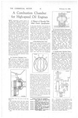
patent No. 440,461 is stated to be particularly suitable for high-speed oil engines, and is disclosed by the wellknown concern, Daimler-Benz Stuttgart-Untertfirkheitn, Germany. As will be seen from the accompanying drawing, the scheme employs a precombustion chamber, a system much favoured by the Daimler-Benz concern. This chamber (2) is located in a watercooled portion of the head, and has the injector (1) placed centrally in it. Between the pre-combustion chamber and the cylinder is a heat-insulated 'plug member (4), through which the burning gases are driven.
The present invention is based on the pa.ticalar form of the passages in this plug; this consists of a number of bores, drilled in such a manner that their axes lie around the periphery of a double cone. These holes terminate in a small recess leading to the cylinder and at the 'upper end in recess 3. It is claimed that the passage of the fuel through the bores ensures complete atomization, and is of considerable assistance when starting from cold.
An Automatic Spragging Gear, prevent a vehicle from running 1backwards on a hill is the primary object of patent No. 440,326, by J. I. and J. H. Booth, " Idris," Lichfield Road, Sutton Coldfield. The device employs a free wheel of the wedging roller or other convenient type, and the patent rests more on the method of application than the use of the free wheel.
The drawing shows the free wheel (1) mounted on the front shaft (2) of the gearbox, that is, between engine and gearbox. The outer race is housed in the gearbox casting, or some other stationary part. The advantage of mounting the free wheel in this position is that the shaft always rotates
B42 in the same direction, and calls for no complicated reversing arrangement in the free wheel. The vehicle is free to move in either direction, as determined by the gear lever, and yet cannot possibly moee in the opposite direction.
The only circumstance in which the engine shaft would turn backwards would be in the event of a backfire, and we presume that the free wheel would be made strong enough to withstand this or the clutch held out.
A Non-deflating Inner Tube.
THE hard going encountered under colonial conditions of operation is probably the reason prompting the design of inner tube shown in patent No. 440,565 by J. Hedley, Hillarys House, Isipingo, Durban, Natal, South Africa. The object is to provide an inner tube that will not completely deflate in the event of a puncture, and this is achieved, as shown in the accompanying drawing, by constructing the tube with a number of separate cells, each extending completely around the periphery, and being provided with its own inflation valve. In the event of a puncture in one section, the walls thereof are immediately pressed together by the pressure in the adjacent chambers, and the tyre maintains its form, although at a reduced pressure.
A further feature is the use of outstanding flaps in each section: these are intended to be blown towards the puncture by the ontrush of air, and so to prevent, or at least diminish, the extent of the deflation.
An Automatic Ignition Adjustment.
FROM the Ford Motor Co„ Ltd., 88, Regent Street, London, W.1, comes patent No. 440,705 describing modifications to automatic ignition-advance devices. In this scheme the control iS divided between centrifugal weights and the suction value in the intake manifold. For acceleration after idling, the idevice gives an instant advance of about two degrees, without waiting for the centrifugal weights to come into action, whilst as the engine speeds up, the centrifugal mechanism takes charge although still subject to control front the suction.
A Variable-stroke Injection Pump. pATENT No. 440,583 describes provements to the type of injection pump in which regulation is effected by varying the length of the plunger stroke; the patentee is F. Cassani, Este. Padova, Italy. Referring to the accompanying drawing, the pump motion originates in a cam (2) which operates a rocking-bar (4) and causes movement of a tappet member (5). The ascent of this tappet directly operates a plunger (6), and continues its motion until forcibly stopped by abutting against an adjustable wedge
(1). Thereafter, the remaining cam lift is expended in compression of the spring (3) under the fulcrum of 4. It is further claimed that this spring acts as a kind of mechanical safetyvalve, and will come into action in the event of an obstructed injector. The system is stated to allow much longer useful life of the pump, whilst providing a more tranquil injection.