


MAKING BEST USE OF THE FORD.
Page 55
If you've noticed an error in this article please click here to report it so we can fix it.
Valuable Advice on Every Phase of Ford Transport which will Appeal to the Owner, Driver and Repairer.
466.—A Coil Box Repair.
The over-zeNlous driver or mechanic rutty tighten unduly the magneto or battery binding post on the old •type switch with coil box, thus fracturing the soldered-on wire at the inner end of the post. Usually this means removing the entire coil box, taking it to pieces, and resoldering the fractured joint. Often a longer wire has to be fitted, as the broken one sometimes proves too short.
To avoid all this trouble, a simple repair can he made by using Magnetic Auudgo, which is a metal-impregnated plitty used by wireless enthusiasts for fixing crystals in their cups. This cornpound should be pressed well into the recessed hole inside the coil box, and will make a perfect contact with the wire. There are two posts, either of which may be in fault.
467.—Simplifying Valve Extraction.
The standard valve lifter supplied with the Ford repair kit consists of a long forked arm and a double-ended metal hook. This hook is designed for use on the manifold clamps when they are in situ. In the majority of cases, however, the manifold and its clamps are removed in order to clean out the ports, leaving only the clamp studs, and the standard hook is not an ideal tool for use in these circumstances.
A useful improvement can be made by discarding the hook and employing an ordinary swivel link, such as that used on the chains of horse traces. The large end is placed over a clamp stud, whilst the smaller will just accommodate the lifting bar, and the-bar can be swivelled round to suit each valve in turn, the link, of course, being moved to whichever of the four studs is mo`st convenient.
468.—Running-in Tight Engines.
No doubt many of our readers have experienced difficulty in starting engines after they have been overhauled. To facilitate this one of our contributors has devised a starting rig, which is also used for running-in.
In constructing this rig, an old Ford elnissis is required. This • can be 'obtained for p. small sum of from 1.5 to £10. It is essential that the engine be in fair order. The driving-shaft tube must be taken out to make room for the stiff engine, as shown in the illustration, and the Foid petrol tank must be removed and another tank fitted on the dash. An old petrol can will serve quite well if a nipple be soldered into it.
For connecting up the two engines, it is necessary to secure an old drive shaft, out about 9 ins, off the square end and file a second square on the short length to fit a second universal joint, as two will be required in case the engines are
not in perfect alignment. A piece of wood, 4 his. by 2 ins., and a tight tit in the chassis, will be required to carry the fron:" of the engine, an old-type crankcase suppert being bolted to the timber. A long starting crank should be made to assist in driving the engine when a start is being made, and, of course, the reverse gear of the running engine should be employed so that both operate clockwise. When iu use, the reverse pedal can be held down by a piece of wood, whilst the stiff engine should be in top gear.
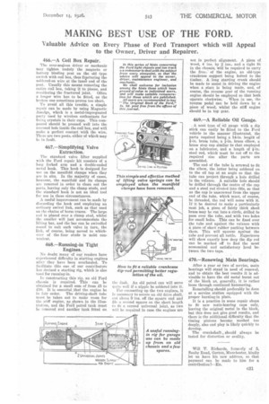
469.—A Reliable Oil Gauge.
A neat type of oil gauge with a dip stick can easily be fitted to the Ford vehicle in the manner illustrated, the parts required being a 14-in, length of Fin. brass tube, a i-in. brass elbow, a brass stop cap similar to that employed on a lubricator, and a length of i-in. steel rod, which must be cut off to the required size after the parts are assembled.
The end of the tube is screwed to fit the elbow, the latter being soldered on to the oil tap at an angle so that the tube can project through a hole drilled in the valance. A suitable hole should be drilled through the centre of the cap and a steel rod riveted into this, so that as the cap is unscrewed from the upper end of the tube, which must, of course, be threaded, the rod will come with it. If it be desired to make a particularly neat job, a piece of fairly thick sheet brass may be cut into a circle, drilled to pass over the tube, and with two holes for small bolts. This can be fixed over the tube and against the valance with a piece of sheet rubber packing between them. This will squeeze against the tube and prevent all rattle. Experience will show exactly how deep the dip rod can be marked off to find the most economical and satisfactory level between the two taps.
470.—Renewing Main Bearings.
After a year or two of service, main bearings will stand in need of renewal, and to obtain the best results it is advisable to have the old metal burnt out of the block as, generally, it is rather loose through continued hammering.
Remetalling should preferably be done at a service station equipped with the proper burning-in plate.
It is a practice in some repair shops to fit new main-bearing caps only, leaving the original metal in the block, but this does not give good results, and there is the additional difficulty that the timing pinions become meshed too deeply, also end play is likely quickly to develop.
The crankshaft, should always be tested for distortion or ovality.