


HINTS ON OVERHAULING.
Page 10
Page 11
Page 12
Page 13
Page 14
If you've noticed an error in this article please click here to report it so we can fix it.
(1) How to Tackle the J-Type Thornycroft. Pointers from the Makers' Repair Shop Practice. What to Look For, and How to Put it Right.
IN THIS, and in subsequent articles which will deal with well-known vehicles of various makes,
it is our intention to describe, for the benefit of those of ourreaders who may wish to undertake a complete overhaul, the best way of setting about the job. While we realize that we number amongst our regular adherents some ex
perts to whom) "bunts on
• overhauling" may be unnecessary, we believe that there are •many more who will welcome this information, which has been culled from the makers' specialized experience with their own products.
In compiling this information, we have been privileged to have full access to the makers' repair shops, to observe their practice, and to consult their expel ienced officials, and we -therefore present the collected information to our readers , with the utmost confidence. We are also able, by the courtesy of the ulakers, to illustrate, for the first time, certain devii3es a:d expedients which they have found to be of assistance in the execution of repaire, of various kinds, and which others, doubtlesg, will be glad to make and use.
In dealing with the question of overhaul, we shall presume, on the part of our readers, -the possession of, and a general familiarity with, the particular type of vehicle with which, for the time being, we are dealing. In these days of excellent and reliable machines, of strenuous haulage competition, and the continu
ous service which these factors make both possible and necessary, it often happens that familiarity with a vehicle is a matter of externals only. Pressure of work, and a diversity of makes and types, often prohibit ,an expert knowledge of the internal construction and the mechanical peculiarities of a particular machine, and even the repair shop engineer and mechanic is liable frequently to receive for overhaul a machine with the internals of which he cannot
claim an intimate acquaintance. In consequence, it is easy to waste a considerable amount of time by noti tackling a job, at the start, in the best possible way. For this reason we propose to go somewhat carefully into the question -qf dismantlement, in order to enable time-wasting pitfalls,and mistakes to he avoided. For the rest, we do not propose to attempt a general treatise on the principles of repair-shop practice, but to confine ourselves to drawing attention to points which should receive special attention in the particular vehicle dealt with and the methods which should preferably be used.
The J-type Thornycroft is one of the most widely used chassis that has been produced by the Basing= stoke concern and we do not doubt that many of our readers are obtaining excellent service from these vehicles in every corner of the world, throughout which that famous name is synonymous with
sound and solid .engineering products. There Comes a time, however, when even, the finest vehicles have to come to the repair shop, and a period in their existence when a thorough general overhaul and examination are desirable, even if only for the purpose of reassurance as to
their general fitness. As in the case of human beings, to whom, even when in the best of health, a thorough " vetting "is a source of added confidence, and -often a means of Averting some tendency by which the health may later be impaired, so in.-the case of 'the motor vehicle. , Moreover, just. as the main cause of failure in health is neglect or abuse in some form or another, se it is in the case of the mechanism of the modern lorry. A thorough overhaul is often an excellent ,lesson in maintenance shortcomings. As a matter of fact,so high a standard of durability has now been attained in most well-known' makes, that a visit to the repair shop is generally evidence either of an accident or of neglect—especially in the matter of lubrication—or of abuse. it is, therefore, not surprising that in our investigation of the J type Thornycroft, we have come across no outstanding and chronic, weakness in the design which is liable to be encountered by users in general, or . do we anticipate that we shall do so in other makes. Obviously, no maker could allow such a weakness to remain in his design, and modern material militates against excessive wear and liability to failure except again—that due to accident or neglect.
Messrs. J. I. Thonrycroft have recently completed the reconditioning of a large number of lorries which
had been through the gruelling test of war service, and it is largely upon that experience that the foregoing remarks are based.
The Sequence of "Take-down "'Operations.
Presuming that the body has been removed, the chassis should be thoroughly cleaned, so tha,t the risk of dirt getting into the various units is minimized. ' The cleaning •is really a difficult operation, and its importance is not. often sufficiently realized. The various units should again be cleaned after re-. moval from the chassis but before dismantling. It is then best to commence dismantlement from the front end of the chassis. Sooner or later, during the process, the wings will get in the way, so they had better • be removed at once. The radiator then claims attention. To take this down, the bolts which hold the bonnet in. position must first be taken out and the bonnet removed. The 'bonnet boards also must come off, three coach bolts hold them down on either side. The starting handle comes next ; slack off the clip bolt and pull it off the square on the shaft. The water joint connections from the engine must next be undone, and the radiator can then be slid off over the starting handle shaft, after the two bolts which hold the trunnion brackets to the frarde on either side have been taken out.
The removal of the steering column is the next job to tackle. First cast off the control connections, and then slack off the bolt in the steering tube 'bottom phee. The column and wheel can then be slipped off, leaving the steering box still in position. This enables the dash to be removed, which is a simple matter of undoing the bolts which hold it to the frame. Care must be taken, however, first to cast off the controls and pipes which connect the dash with other parts.
The steering box is now get-at-able, and it can be removed at once if .desired. It will, in any case, have to be dismounted before the engine can be taken out of the frame. There is no need to Undo the bolts which hold the box to the bracket which carries it. Undo the three bolts in the bracket foot .take off the leather cover from the ball joint on th end steering drop arm and east loose the fore and aft steering rod. The steering box with its bracke can then be lifted out.
The next unit to receive attention should be the rear axle. This is desirable on account of the fac that, with an unloaded chassis, the spring cambe Throws the propeller shaft and its disc joints slightly in compression. The flexion of the leather disc under these conditions, and presence of the shroud on the disc joint fork, makes it very difficult to un couple the joints, and slide out the propeller shaft to enable the gearbox to he lifted out. The reas axle should therefore be tackled fir,st.
The brake rods should he first of all uncoupled. Then takeoff the nuts from the four bolts which hold each rear spring on the spring pain], and lift up the back of the chassis to enable the dowel centre pins in the springs-to clear the holes in the palms in which they rest. It is easy to forget the existence of this dowel.
About 1 in. lift is necessary, and the axle can then be moved back suffi
ciently to allow the rear disc ueiversal joint to be uncoupled. It is then a simple matter to uncouple the .propeller shaft at the front end, and to remove it.
Attention can now be given to the gearbox. Four bolts hold this to the sub-frame, and the only ob stacles to its removal, after these have been taken out, are the leather disc joint which connects it to the clutch shaft and the bearing bracket which carries the change speed shaft. If necessary, the change speed gate and brake quadrant and all the gear can be removed simultaneously with the gearbox, but it is better to take off the two nuts which hold the change speed shaft bearing bracket to the box and swing it loose, and remove the gearbox first. Before lifting it out, the foot brake gear must, of course, be disconnected, and before dismounting the clutch, the pedal cross-shaft must, obviously, come down, and then the clutch comes out easily enough after the nuts which clamp the leaf springs to the flywheel have been removed.
Here it may be opportune to interject a word of
The special sling for lifting
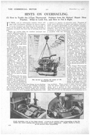
The next step is to take off the flywheel; it comes off easily enough by taking out four bolts. It is better to do this while the engine is in the chassis, as it is heavy and its removal enables the engine to be ." slung with safety and with ease.
The engine can now be taken out, after uncoupling the exhaust pipe and taking out the holding-downbolts. The chief point to observe is the method of slinging; Messrs. Thornyeroft have devised a. sixnp-le, and very useful, form of sling, of which we give a sketch, and which it is well worth while to make. There are -two bars, which catch the engine under the valve pockets on either side, that on the off side having a bend in it to clear the hot air pipe-. The chain from one end of the near side bar couples to the other end of the off side bar, and vice versa, so that the chains can be crossed on the crane hook. This enables the engine to be slung without damaging or removing any of its fittings.
The chassis is now practically dismantled, save for the front axle; Undo the spring bolts and jack up the front of the frame (as in thp case of the rear axle), to enable the dowel pins to clear the holes in the spring palms. The axle can then be slid out forwards, with the fore and aft steering rod trailing behind it. The frame meanwhile will of course have been packed up on trestles. We are now left with the frame with all its brackets, and the springs still in position. The latter can be taken off, and dismantlement is then complete. Two men should be able to accomplish this in about three hours.
Points to Bear in Mind.
The Thornycroft frame is particularly robust, so, unless a vehicle has been used under very abnormal conditions, it is unnecessary to examine the frame for cracks. All rivets should be tapped for looseness, particularly those in the subfrarne and apron plate. Should a loose rivet be found, generally speaking no .attempt should be made to replace it by another. Drill out the hole and replace the rivet by a good quality, well-fitting bright bolt.
The condition of the springs should have been examined as to .camber before the chassis is dismantled.One cracked plate in a spring generally denotes-, something wrong throughout. Unless a skilled springsmith is available, it is better not to attempt t8 repair or " set up " springs. It is a specialist's job, and they should be returned to makers for repair, or replaced by new ones. If all plates are sound, examine spring eyes for wear. They are bushed at the front ends only, and eicessive wear, if found, is practically certain to he due to neglect in lubrication. See that greaser holes are not blocked up. Examine particularly the bottom pin in the rear spring rear shackles. If that is not lubricated properly, it may seize in the shackle. The ‘pin will then shear the dowel, which locates it in the bracket, • a n d oscillate therein on narrow bearing surface. Thig Tri ay cause wear and possibly the scrapping of the bracket. Examine the springs for
" dryness." I f
necessary, r move the the clips and prise apart, 'or slide leaves sideways around' the centre pin and grease them well.
The silencer should be cleaned out and the holes in. the baffle plates cleared. This is a simple matte; as a long rod passes right through it from end to end, and the removal of the end nuts enables the whole unit to be taken to bits.
The rivets on the front and rear wheels should be examined for tightness. Generally speaking, it is unlikely that any serious wear will have taken place in the wheel centres, as the bearings are of such ample dimensions. . It Should be noted that, if necessary, oversize bushes can be obtained from the makers. There may be some side play ; that can be taken up by placing planished steel wagiers (also obtainable from, makers) behind the inner bronze thrust washers with which the front and rear wheels are provided.
Overhauling the Units.
As mentioned at the commencement of this article, it is not our intention—even if space permitted— to enter exhaustively into all the details' of repair, but chiefly to draw attention -to special points and peculiarities of the particular vehicle under -consideration.
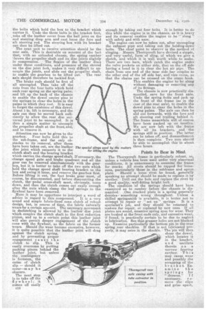
The J type Thornycroft engine is a sturdy unit, and it seldom needs extensive repair. For examination purposes, both pairs of cylinders, with induction and exhaust Manifolds and fittings, can be lifted bodily when the six nuts on each cylinder base have been removed -and the fan b.elt disconnected. Care should be taken not to cause piston distortion when removing the gudgeon pins. The makers employ a useful tool for this purpose, which we illustrate, and which repairers might easily •make. The illustration is self-explanatory.
All the big:end and main bearings are die castings, which the makers supply both in standard and undersizes for re-ground crankshafts. The bigend bearings in 10, 20, 30, 40, and 50 thousandths undersizes and the mains in 3 undersizes 10, 20, and i0 'thousandths respectively. It should be noted that they undertake to grind worn crankshaf In to standard undersize dimensions, and aiso to re-grind worn cylinders to standard oversizes, and to supply oversize pistons to suit. Ten and tWenty thousandths respeetively are the two oversize standards. Valves having stems 1-32 in. oversize diameter are also supplied. .
If end play is found in the crankshaft, it is due to wear on the flanges, of the die-cast main bearings, and, if it be excessive, they must be replated.End play on the camshaft can be taken up by " letting up" the half-time wheel on its taper. It should be. noted that the bearings in which the water pump spindle runs are made of special white metal. If these bearings are worn sufficiently to need renewal, the same grade of white. metal should be obtained from the makers for the purpose.
Gearbox Generalities.
Unless a vehicle has been badly handled, gears are unlikely to need replacement. That question, as also that of the conditions of bearings and so forth, is a, matter for the repairer'sjudgment. Care should be taken when re-assembling the gearbox to allow 1-32 in, end play in the layshaft. The ball thrust washer which is carried in a housing at the rear of the box should be given three thousandths of an inch clearance, and its positioning should be carefully watched, so that it is not " pinched " therein. The spigot on the end of the main shaft should have from five to seven thousandths clearance in its bush.
On some gearboxes the reverse pinion gets its lubrication by means of a hole drilled in the pinion boss. This is not the most satisfactory method, and. where a pinion of this type is found to be fitted, it is a good plan to plug the hole and te drill one hole up the centre of the reverse spindle, and another radially through its side to meet. it, so that lubricant can find its way to the pinion in that manner.
Rear Axle Durability.
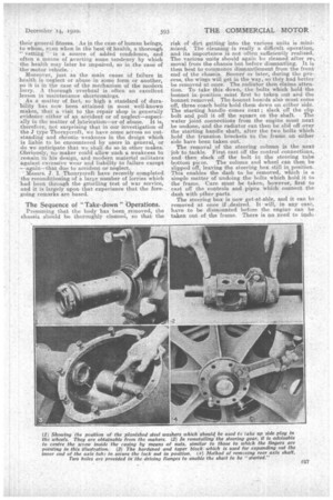
Excepting in rare cases of inexcusable neglect, in which the rear axle worm is allowed to run absolutely "dry," the worm and wheel are practically everlasting, and the question of replacement, therefore, does not require consideration. It should be "noted that in most cases (dependent upon the type of body fitted), the worm, wheel, and differential gear can be ,removed from the axle for inspection when the latter is in position on the chassis. The axle shafts must first be removed, in the manner shown in one of the illustrations accompanying this article.
The removal and replacement of axle tubes is the most difficult operation likely to confront the repairer. We therefore illustrate specially designed devices to enable this to be easily accomplished. The upper illustration on the previous page shows the method of extracting the axle sleeve. The operations are as follow :—First chip throtigh and remove the nut on the inside end of the sleeve ; this cannot be unscrewed, as the end of the tube has beet expanded inside it. Then slip extractor tube (C) over the axle sleeve and pass bolt (D) through the sleeve. Place collar (E) over the threadon the end of the sleeve Two neck bushes (F) and (G) are also required that marked F has an external diameter the same size as collar E, which is slightly smaller than the bore of the casing.. Bush F is placed on the extractor bolt,
i as shown n the sketch, and the nut pet on. On the other end of the bolt is placed the spigot-block (H) and its nut. The spigot on this block slips inside the end of the extractor tube. By screwing up the nut at this end of the bolt with a long spanner the sleeve can be withdrawn from the,easing to a position where it is sufficiently loose to be taken out by hand.
The Method of pressing the sleeves into the casing is also shown. The bores of the ca-sing and the ends of the sleeves should first be liberally coated with red or white lead paint. The sleeves can be placed in positionin the casing by hand, and then they can be pulled into-the casing by using the draw bolt and collars shown in the sketch. The large spigot plate (K) should first be bolted securely to the axle casing in the position normally occupied, by thetop worm gear casing, in order to prevent distortion of the former. The two collars (L) should be placed over the outer screwed portions of the two sleeves. The two neck bushes (G) should then be placed in position and the draw bolt (N) passed through the lot, and the nut screwed on. Beth nuts should be screwed up together until both keys have fairly -entered. the keyways. This matter. of keys properly entering keyways wants watching very carefully. It will be found to be comparatively easy to ensure one key-entering correctly, and with a little care in first tightening both huts at once, the two keys can be made to enter. If, however, one sleeve -slips round a little so that the key and keyways are not in line, by far the quickest .way is to extract the .sleeve and replace it in line.. No attempt should he made to turn the sleeve in the axle casing to line-up key and keyway. When both keys have fairly, entered each sleeve can be pulled home separately. A gauge should. be used for testingwhether the sleeve is right home or not., so that the correct distance from the face of: the flange of. the axle. casing to the end of the plain portion of the sleeve is ensured It should be noted that when an-axle sleeve has been-replaced, the inner ends.of the sleeves should be opened out inside the lock-nuts by means of a taper drift.
The brake gear calla, for no special -comment, as there is no peculiarity about it. Relining the shoes is a fairly straightforward job. - A Novel Steering Gear,
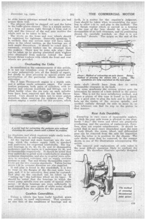
The Thornycroft steering box is unique in the employment of a steering screw working in a white metal " nut " formed by running white metal around the screw inside a shell. This type of construction makes it particularly easy for any. backlash, which may occur after extensive use, to be taken up, and it is a job which most repairshops can tackle. The great point to observe in remetalling is to centre the screw accurately in the shell which holds the white metal before pouring. A nut at either end, as shown in one of the illustrations, will ensure this. Apart from thi4 precaution, the usual procedure in remetalling bearings can be followed, the metal being poured through one of the holes with which the shell is drilled. The other holes should, of course, be blanked externally with • clay while the operation is being carried out.