


Abridgments of Interesting Patent Specifications.
Page 24
If you've noticed an error in this article please click here to report it so we can fix it.
Speed Indicator ; Vulcanisers ; Lubricator ; Engine.
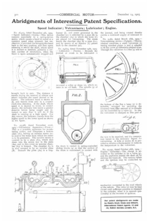
No. 26,415, dated December 5th, 1904. —Speed Indicator.—Collie.—This device consists essentially in a spring-driven motor, which causes a hand to travel at a constant speed when released, but mechanism is provided for bringing this hand back to the zero position, and then again releasing it whilst the shaft, whose speed it is desired to measure, performs a certain number of revolutions, when the hand is again automatically stopped and
brought back to zero. The distance it travels during the interval of release and return indicates the speed desired to be known. The indicator hand is shown at 26, and travels from zero in a counter clock-wise direction. If the shaft, whose speed it is desired to know, is rotated slowly, the indicator will travel a greater distance before being caught and returned to zero than it will do if the shaft is rotating at a high speed. For this reason, the indicator travels from the higher speed to the lower speed as shown in the figure.
No. 25,368, dated November sand, i9o4,—Vulcanising Apparatus—Frost.This is a portable apparatus for re-rubbering covers, and comprises a bottom plate (As), having an annular recess (au) to receive the water from which the steam is to be generated. The annular recess is covered in by a plate (At), which dips down into the recess (at) in the plate (A2), and in this cover an annular chamber (A3) is formed. The chamber A3 is in turn covered in by an annular plate ,(13). Beneath the plate (A2) is a ring burner (J), and steam generated in the chamber (al) is admitted by a pipe (K) to the chamber (A3) in which the tyres (C) are placed for vulcanising. The steam leaves the chamber (A3) by a pipe (Li), and by means of an injector (L) passes back to the chamber (at).
No. 24,674, dated November r4th, 1904. — Lubricator. — Proctor. — Beneath the journal or crank to be lubricated is mounted a roller or drum (2), which rotates in an oil bath. The spindle (3) of the drum is carried in spring-controlled sliding blocks (4) so that the surface of the drum is maintained in contact with I,
the journal, and being rotated thereby carries a continual supply of lubricant to it.
No. 5,580, dated March i6th, Tyre-repairing device.—Padgett.—This invention comprises a small vulcaniser (I) having recessed plates (2 and 3) adapted to fit the curve of differently-shaped tyres. Through the vulcaniser is a flue (4) and at the bottom of the flue a lamp (5) is detachable, mounted for providing the necessary heat he amount of in-draught can be controlled by a valve (7). In use, the vulcaniser is clamped to that part of
the tyre to be repaired, and the temperature raised to the necessary degree for vulcanising. A hole or recess (8) is provided to receive a thermometer to indicate the temperature in the vulcaniser.
No. 23,037, dated October 26th, r904.— Engine.—Eckersley.--The charge is admitted to the cylinder (e) by a valve (g), and the explosion rotates the shaft (d) by striking the vanes (b). The various valves and the ignition may be controlled by mechanism connected to the road wheels of the vehicle. The valve (j) may be kept closed until sufficient pressure is obtained 'n the cylinder, when it is opened—presumably at the moment of ignition.