


NOVEL CHASSIS CONSTRUCTION.
Page 28
If you've noticed an error in this article please click here to report it so we can fix it.
A Résumé of Recently Published Patents.
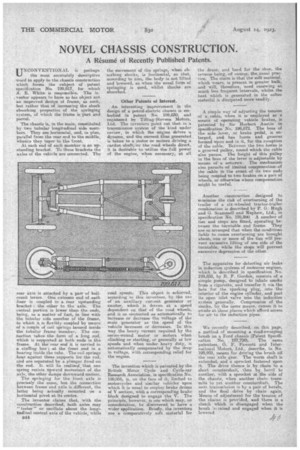
UNCONVENTIONAL is perhaps the most accurately descriptive word to apply to the chassis construction which forms the subject of patent specification No. 199,817, for which A. E. White is responsible. The in. venter appears to have as his object not an improved design of frame, as such,. but rather that of increasing the shock absorbing properties of the springing system, of which the frame is part and parcel.
The chassis is, in the main, constituted by two tubular longitudinal side meinhers. They are horizontal, and, in plan, parallel from the rear end to the middle, whence they taper to the front.
At each end of each member is an upstanding bracket.. To these brackets the axles of the vehicle are oonnected. The
rear axie is attached by a pair of bellcrank levers. One extreme end of each liner is coupled to a. rear upstanding bracket : the other to the axle. The central portion is lower than the ends, being, as a matter of fact, in line with the tubular side member of the frame, to which it is flexibly coupled by means of a couple of coil springs housed inside the tubular frame member. The connection takes the form of a long rod, which is supported at both ends in the frame. At, the rear end it is tarried in a stuffing box ; at the front end in a bearing inside the tube.. The coil springs bear against theee supports for the rod, and are separated by a plunger fixed -on the rod. It will be realised that one spring resists upward movement of the axle, the other damps downward niotion.
The springing for the front axle is precisely the same, but the connection between frame and axle is different, the latter being actually mounted on a horizontal pivot at its centre.
The inventor claims that, with the construction described, both axles may " teeter" or oscillate about the longitudinal central axis of the vehicle, while B44 the movement of the springs, when absorbing shocks, is horizontal, so that, acoording to him, the body is not lifted and lowered, as when the usual form of springing is used, whilst shocks are absorbed.
Other Patents of Interest.
An interesting improvement in the design of a petrel-electric chassis is embodied in patent No. 199,830, and registered by Tilling-Stevens Motors, Ltd. The inventors point out that in a transmission system of the 'kind 'ander review, in which, the engine drives 'a dynamo, and the current thus generated is taken to a motor or motors driving a cardan shaft, or the road wheels direct, it is desirable to utilize the full power of the engine, when necessary, at all read spe: te This object is achieved, accord]: ie this invention, by the use of an auxiliary current, generator or exciter, which is driven at a speed dependent on that of the road wheels, and is so connected as automatically to increase or decrease the voltage of the main generator as the speed of the vehicle increases or decreases. In this way the heavy current required by the series-wound motor or motors when climbing or starting, or generally at low speeds and when under heavy duty, is automatically compensated by the drop in voltage, with corresponding relief for the engine.
The invention which is patented by the British Motor Cycle and Cycle-ear Research Association, in specification No. 199,956, is, on the face of it, limited to motorcycles and similar vehicles upon which it is usual to employ brake drums of V eection, with a corresponding brake block designed to engage the, V. The principle, however, is one which may, on consideration, he discovered to have a wider application. Briefly, the inventors use a comparatively soft material for the drum, and hard for the shoe, the reverse being, of course, the-usual practice. The claim is that the soft material, which wears, is present in greater bulk, and will, therefore, need renewing at math less. frequent intervals, whilst the heat which is generated in the softer material is dissipated more readily.
A simple way of adjusting the tension of a. cable, when it is employed as a means of operating vehicle brakes, is patented by Sir Herbert Austin in specification No. 199,872. The boss of the side lever, or brake pedal, is enlarged, and has horns and grooves formed upon and in it, for the reception of the cable. Between the two horns is a grooved pulley, round which the cable also passes. The height of this pulley in the boss of the lever is adjustable by means of a setsevew. The mechanism also permits -of limited compensation.: of the cable in the event of its two ends being coupled to two brakes on a pair of wheels, or otherwise where compensation might be usefuL Another construction designed to minimise the risk of overturning of the trailer of a six-wheeled tractor-trailer combination is described by R G.: Hugh and G. Seammell and Nephew, Ltd., m specification No. 199,890. 4 number of ties and stops are fitted, operating between the turntable and frame. They are so arranged that when the conditions liable to cause overturning are brought about, one or more of the ties will Prevent excessive lifting of one side of the turntable, while the steps will prevent excessive. depression of the other.
The apparatus for -detecting air leaks in induction systems of motorcar engines, which is described in specification No. 199,858, by R. F. Gordon, coneists of a simple _pump, designed to inhale smoke from a. cigarette, and transfer it via the hole for the sparking plug, into the interior oh the engine cylinder, and past its open inlet valve into the induction • system generally. Compression of the smoke, by the same means, causes it to exude at those places which afford access for air to the induction pipes.
We recently described, on this page, a method of mounting a road-sweeping brush on a Ford chassis (Patent Specification No. 197,7201. The same patentees. G. F. Fawcett and International Motors. Ltd., describe, in No. 199,903, means for driving the brush off the rear axle gear. The worm shaft is extended, and a sprocket fastened upon it.. The drive thence is by chain to a short coanterahaft, then by bevel to another, with a sprocket at the side of the chassis, when another chain transmits to yet another countershaft. The next transmission is by a pair of bevels, and the final drive by chain again. .14feens of adjustment for the tension of the chains is provided, and there is a clutch which is disengaged when the brush israised and engaged when it is lowered