


411.—Removing and Replacing the Wheels and Axles of Steam Wagons.
Page 26
If you've noticed an error in this article please click here to report it so we can fix it.
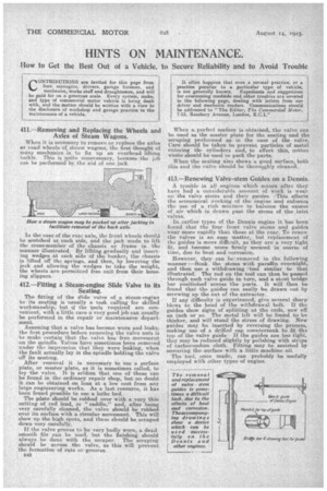
When it is necessary to remove or replace the axles er road wheels of steam wagons, the first thought of many mechanics is to fix up an overhead lifting tackle. This is quite unnecessary, because the job cal., be performed by the aid of one jack.
In the case of the rear axle the front wheels should be scotched at each side, arid the jack made to lift the cross-member of the chassis or frame in the manner illustrated. By lifting gradually and inserting wedges at each side of the hunker, the chassis is lifted off the springs, and then,by lowering' the jack and allowing the wedges to take the weights the wheels are permitted free exit from their housing slippers.
412.—Fitting a Steam-engine Slide Valve to its Seating.
The fitting of the Oide valve of a steam-engine to • its seating is usually a task calling for skilled workmanship; but if the tools required are convenient, with a little care a very good job can usually be performed in the repair or maintenance department.
Assuming that a valve has become worn and leaks, the first procedure before removing the valve nuts is to make certain that the valve has free movement on the spindle. Valves have sometimes been removed under the impression that they were leaking, when the fault actually lay in the spindle holding the valve off its seating.
After removal it is necessary to use a surface plate, or master plate, as it is sometimes called, to try the valve. It is seldom that one of these can be found in the ordinary repair shop, but no doubt can be obtained on loan at a low cost from any large engineering works. As a last resource, it has been found possible to use a lathe bed.
The plate should be rubbed over with a very thin cutting of red lead, or " raddle," and, after being very carefully cleaned, the valve should be rubbed over its surface with a circular movement. This will show up the high spots, and these should be scraped down very carefully.
If the valve proves to be very badly worn, a dead smooth file can be uaed, hut the finishing should always be done with the scraper. The scraping should be across the valve, as this will prevent the formation of ruts or grooves.
When a perfect surface is obtained, the valve can be used as the master plate for the seating and the scraping performed as: in the case of the valve. Care should be taken to prevent particles of metal entering the cylinders and, to effect this, cotton waste should be used to pack the parts.
When the seating also shows a good surface, both this and the valve should be thoroughly cleaned.
413.—Renewing Valve-stem Guides on a Dennis.
A trouble in all engines which occurs after they have had a considerable amount of work is wear
ose the valve stems and their guides.. --This, affects the economical working of the engine and enforces the use of a rich mixture to balance the excess of air which is drawn past the stems of the _inlet valves.
In earlier types of the Dennis engine it has been feund that the four front valve stems and guides
wear more rapidly than those at the rear. To renew the valves is an easy matter, but replacement of the guides is more difficult, as they are a very tight fit, and become more -firmly secured in course of time, due to heat and corrosion.
However, they can be: removed in the following manner :—Soak the stems with paraffin overnight,
and then use a withdrawing 7tool similar to that
illustrated. The rod on the tool can then be passed through each valve guide in turn, and a stout bridge bar positiohede across the ports. It will then be found that the guides can easily be drawn out by screwing up the nut of the extractor.
If any difficulty is experienced, give several sharp blows to the head of the withdrawal halt. If the
guides show signs of splitting at the ends, saw off an inch or so. The metal left will be found to be thicker, and will stand the stress of drawing. New guides may be inserted by reversing the process, making use of a drilled cap countersunk to fit the top of the valve guide. If the guides are too tight, they may be reduced slightly by polishing with strips of carborundum cloth. Fitting may be assisted by smearing the-_surfaxe -with a little machine oil.
The tool, once made, can probably he -usefully employed with other types of engine.