


EQUIPPING A COACH FOR WIRELESS RECEPTION.
Page 12
If you've noticed an error in this article please click here to report it so we can fix it.
The Explanation of the Highly Efficient "Tuned-anode " Method of Highfrequency Amplification is Here Continued.
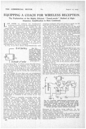
AST WEEK we .outlined the fundamental problems connected with the functioning of one valve when connected to another by the " tuned-anode " method of. coupling. It was pointed out that the real coupling took place through a condenser, but that since it was necessary to make provision for the maintenance of the steady plate current for the supply of positive potential on the anode of the first valve, some means had to be employed that would allow of the passage of a direct or steady current, but would be impervious to the high-frequency currents between the plate and filament of the high-frequency valve. We pointed out that a suitable inductance included in the plate circuit of the first valve could, due to its property of self-inductance, act as we required.
In Fig. 14 we' have shown diagrammatically such
an inductance L1) It will be noted that the inductance is shunted by a condenser (Cl), which, as the arrow drawn across it denotes, is a variable one. Such a circuit, possessing as it does both capacity and inductance, is an oscillatory one, and, moreover, since the capacity can be varied, the circuit (Cl, Li) can be timed. _
It will readily be seen that such an arrangement will pass steady current without loss [other than that due to the ohmic resistance in the coil (Li), which, with' the very small currents handled in practice and the relatively large wire with which these coils are generally wound, is quite negligible], but its resistance, or more correctly its impedence, to alternating or oscillatory currents will depend entirely on their frequency and the value of Cl and Li. By choosing suitable values for these two; the impedence can be -raised to a very high figure, and -if . this be done practically no high-frequency current of the selected waVe length will pats. through, the arransement, and so the effect of connecting a high-tension battery across the plate and: filament of a valve which is Operating on 'high-frequency currents is, when this arrangement is included irk thecircuit; in no Way
deleterious. . .
Fig.: 15 shows a complete receiving circuit employing the " tuned anode" S method of high • frequency amplification. Signals received on the aerial (A) set uphigh-frequency. oscillations in the oscillatory 'circuit (01, Li), which is adjusted by means of the variable: condenser (01). and the variable induetanee (L1), so that its time period shall be the same as that of the frequency of the incoming waves. The resultant high-frequency okillaiions engendered in the circuit (L1, G, F) operate the valve (VI) and cause high-frequency pulses to pass through the plate circuit of the valve (V-1). In. this circuit, however, we have the blocking oscillatory circuit (02, L2), and if this circuit his been adjusted to the. wave brigtii of the incoming signals, none of the highfrequency currentS, will be able to pass it and they will, therefore, be forced to pass through the
s' 28 coupling condenser (03) and across to earth via tho grid (G) and filament (F) of the valve (V2).
The inclusion of the condenser (03) in the grid circuit of the valve (V2) has the effect (as has already been explained) of causkng lopsided pulses to appear in the plate circuit of this valve, and these pulses are able to operate the telephones (T), whereby the electrical phenomena are converted into mechanical movements and are thus rendered -audible. '
111 and 112 are the filament resistances whereby the brightness of the filament of each valve is Independently controlled. 113 is the high-resistance leak. the purpose of which is to relieve the grid of lig of acciimulated charges which would render it partly paralysed, and 04 is the condenser across the telephones for the purpose of preventing the highfrequency .currents. in the plate circuit of V2 from paining through the telephones.
.It will be seen that the grid-leak (113) is not connected across .the Condenser (03), as was shown in previous diagrams, and that, moreover, it is connected to the positive side of the low-tension battery (B1). It cannot, with this method of high-frequency amplification, be connected across the coupling con. denser because, as an inspection of Fig. 15 will show, to do so would be to render it inoperative, since there is no direct connection to earth that way. It is howeVer, connected to the positive andnot the negative, or earth, side of the battery (B1) ill erder• to stabilize the set.
When one attempts to operate two valves coupled together, as in Fig. 15, in the grid circuit of 'each of which—or associated therewith—there is a tuned circuit, it will he found that the arrangement is very unstable and is liable to break out into self-oscillation at the slightest provocation. Moreover, this will take place without any reaction coil being used; the small amount of coupling between the grid and filaments of the valves being sufficient. As has already been emphasized, a receiver must never be allowed to get into this state.
By connecting the grid-leak to the positive, instead of the negative, side of the filament a tiny grid current is caused to flow, and this is generally' sufficient to damp the circuit so as to prevent spontaneous oscillation.