


Multi-wheeled Bogie for Heavy Trailers
Page 36
If you've noticed an error in this article please click here to report it so we can fix it.
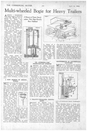
A MULTI WHEELED trailer bogie is shown in patent No. 559,171, by 0. North, P. Hugh, and Scammell Lorries, Ltd., all of Tolpits Lane, Watford West. The advantage of the design is that, in spite of irregularities of ground, the load is evenly distributed over all the wheels.
The drawing shows an eight-wheeled bogie under conditions of artificial stress. The body of the trailer is fitted with upswept girders which reach out over the bogie to carry a cross' member (2) which carries the king-pin about which the bogie swivels. Actually, a ball-ended pin is used so as to allow a limited rock in all directions. The amplitude of movement is controlled by a pair of coil springs (I) with load blocks (3) bearing on a smooth race on the. bogie.
The bogie frame is mounted, primarily, on a pair of rocking beams (I), which are universally jointed on to side girders (5). The latter are centrally piVoted on pins (7), an arrangement that permits " corner-wise " rocking. Each side girder (5) has, pivoted on it, axles (6) which carry the pairs of wheels, so that the whole system is in a state of perfect compensation. The drawing shows one
wheel jacked. up to illustrate the•adaptability of the mounting.
Leaf springs or rubber blocks may be used, where necessary,'to limit A NEW DESIGN OF SPRING WHEEL
AANY have been the attempts in the 1111 past to design a resilient wheel but, when tyres are cheap, there is little incentive to any change. In theSe days, however, the shortage 'of rubber has given a. new impetus to the search for such a device, a
design for which is shown in patent No. 559,023, by Dunlop Rubber Co., Ltd., I. Albany Street, London, N.W.1, and F. King and R. flaw, both of Fort Dunlop.
The drawing shows a section of the pro posed wheel in which ' the wheel itself is turned over at its edge to form an axial flange (3). To.
this is attached a ring (2) upon which are formed pairs of bosses (4). These locate compression springs bearing on external plates (5) which are similarly bossed. The springs are in,itially precompressed to a degree sufficient to withstand normal loading. '
Each external plate (5), of which there are 20, is hinged to its neighbour by means of a rubber-bushed pin, so that dirt and water cannot enter the joints, and wear will be averted.A thin rubber tread (1) may be fitted on the outside of each plate if— desired.
OIL ATOMIZER FOR PRODUCER-GAS ENGINES
ADEVICE for adding heavy-oil vapour, to the intake of an engine operating on producer-gas, is shown • in patent No, 558,903; by David Alan and Co.., 18, South End, London, W.8. The device comprises a fuel container and a :Mixing apparatus both in . the same casing.
Referring to the drawing, the body of the ;device holds the oil,' Which is introduced via a .filler-plug at the top. The effect of gravity and engine suction is to cause a small quantity to descend through a filter, (3), soak through a wick (4). And emerge _into a chamber (5), which is filled with wool.. Here it•meets an air supply which has, been drawn in through a filter (I) and a central Aube (2). The resulting mixture is then drawn through another filter (7), past, an adjustable needlevalve (6) and, finally; travels .to the' intake of the engine .via pipe S.
GRAVITY-OPERATED TIPPING , BODY
PAT EN T No. 558,777, from F. Greenwood, 94, Clarendon Road, Morecambe, Lanes, covers a tipping body in which the load is permitted to he self-tipping. In the design described, the body rests upon a sub-frame which
• is divided into, two parts, a fixed portion at the front end and a pivoted section at the rear. The body rests on rollers, and can be moved to the rear by means ef a long screw located centrally, under the body. A handle is provided at the side to turn this screw, which moves the body rearwardly until it overbalances on the pivoted portion. The speed of tipping is controlled bydampers which appear to be of the hydraulic cylinder-and-piston type.
Another feature is the use of a cable which is pulled by the tipping action, and gives the main screw a few extra turns; this causes a last-moment increase in the angle of tip, and assists to discharge the load. To haul the body back on to the vehicle, a hand-operated cable winch is 'provided at the front.
REFINEMENTS IN CENTRIFUGAL CLUTCHES
ARANS for simplifying the mechanLIU ism of an automatic centrifugal clutch form the chief object of a design shown in patent No. 5.59,123, by Borg and BeckCo., Ltd., and L. Godfrey,
both of Tachbrook Road, Leafifington Spa. .
The drawing shows a lower halfsection of the clutch, which is fitted with the usual manual withdrawal mechanism, comprising a thrust-ring y and fingers (2) pivoting on pins (3). On the same pins are also pivoted centrifugal intensifiers, consisting of bob-weights (4) attached to curved fingers (5). The latter impinge on pads on the presser-plate bosses (8) which project through the casing. To prevent rattle, when unloaded, both the manual and centrifugal units are biased by light springs.