


EXTRA BRAKING POWER FOR HEAVY LORRIES.
Page 9
If you've noticed an error in this article please click here to report it so we can fix it.
A Simple Lever Device for Incorporating in Brake Application Systems for Increasing Pedal Leverage Without Extending the Arc of Pedal Movement.
TN VIEW of the fact that the tendkency with commercial goods vehicles is in the direction of greater carrying capacity and heavier loads, whilst there is a ranid extension of the use of sixwheelers and of trailers, the time appears ripe for the consideration of some suitable means for easing the operation of brake application by a reduction of the effort required, at the same time giving greater efficiency in braking power.
On the introduction of front-wheel brakes to pleasure cars many were led to believe that the usual pressure applied simultaneously to four brakes, either by foot or hand lever, would result in a greater braking effect, but experience has proved that two sets of brakes acting together require each the same total pressure as if they were ap plied separately. In other Words, it takes twice the effort to apply front and rear brakes simultaneously that it would require to apply either pair singly. It is, therefore, evident that, if four-wheel brakes are applied to commercial motors, it will be necessary to consider some means of augmenting the power of the driver in their application.
Various forms of assistance are offered in such devices as Servo brakes and brakes operated by fluids—either air, vacuum or oil. There seems, however, a desire on the part of both manufacturers and users to stick to something which is purely mechanical. For land brakes there is the "more than one pull" system, used with succesi on steam wagons and trailers, iu which the
driver is provided with a leverage of greater power than can be applied through the somewhat limited are described in a single pull by his hand
lever. That is to say, when he has willed his lever so
far back as he is able, he can, by a special contrivance of ratchet teeth, thrust his lever forward and then take a second or third pull. Such a brake is of great value when descending long hills, but is hardly suited to traffic needs when, for example, a sudden stop is made necessary by some other vehicle obstructing the road. With the foot brake the designer is between two fires, as, if he increases the leverage, by lengthening the levers which actuate the expander cams, it is necessaryto increase the arc described by the pedal.
Unless he does that there is the danger of the brake pedal coming down on the footboard before the brake is fully applied, whilst, if he increases the are of movement of the pedal, he makes matters very awkward for the driver wo has to lift his foot to an unreason able height. A recently protected device, which may •be called a brake " booster," is of interest on account of its simplicity.
The object of the device is to hasten the first part of the movement necessary for the application elf brakes, and by so doing allow greater leverage to be employed without lengthening the arc described by the band or foot lever.
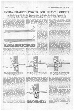
In the case of, say, a foot brake, the first part of the movement of the lever is necessary to bring the shoes in contact with the drums, and to take up all backlash and spring in levers and other parts. Now, it is clear that this movement is more or less an idle one, rend that there is no resistance offered other than the slight pull necessary to extend the springs which hold the brakes off. To overcome this slight resistance, it is not necessary to have a..very powerful leverage, as quick movement rather than power is what is required. So soon as this idle movement is completed, the greater the, leverage that can be conveniently obtained the better. Fig. 1 is a general view, showing the usual leverage obtained, whilst Fig. 2 shows how ,this leverage can be increased, by the incorporation of the "booster,", to nearly double, without increasing the arc described by the pedal. Fig. 6 is a view of the device with one of its side plates removed. The bell-crank (B) is seen to be at such an angle that, when the rod (P) is pulled by means of the pedal, it imparts to the rod (It) an accelerated or "hustled" movement until the tail of the bell-crank lies parallel with the two rods ; after this, the movement of the rod (P) and the resultant force transmitted by the rod (R) are equal.
Fig., 2 shows the position of the devicewhen the brake is off ; Fig. 4 shows the position when the rod (P) has moved f in. and has caused a movement of 14 ins, in the rod (R), whilst Fig. 5 shows that, when the idle movement has taken place, all further movement and power transmitted from P to It are as if they wore coupled together.
We understand that the Rex Transmission Co., of 3, Portsmouth Street, London, E.C.2, are concessionnaires for the device.