


ANOTHER BRITISH ADDIT
Page 16
Page 17
Page 18
Page 19
If you've noticed an error in this article please click here to report it so we can fix it.
--)SIX-WHEELERDESIGN
First Published Details of a New Karri( which Embodies Many of the Features Adv( which has Remarkable Capabilities and veral Years by "The Commercial Motor."
THERE ARE indications in several directions that some British manufacturers are at last fully awake to the far-reaching potentialities of the. multi-wheel vehicle of the type which has been recommended by this journal for many years, i.e., that having a rigid frame, as distinct from the tractor-trailer type which was developed purely as a -method of increasing the load-haulage capacity of a single power unit. The rigid-frame six-wheeler, on the other hand, has already been conclusively _proved greatly to lessen the wear on road surfaces and damage to foundations, not only by spreading the load over a greater number of wheels, but by inherent advantages in the best designs by which impact is reduced to a quarter of that on each rear wheel of an ordinary-type vehicle. At the same Lime, it is a comparatively easy matter so to design a, multi-wheel chassis that the driving and braking stresses are spread over at least four out of six wheels ; in fact, six-wheelers which both drive and brake through all wheels have already been developed.
However, in this article we do not wish to go over old ground, but to deal in particular with a remarkably successful type
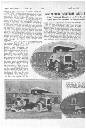
known as the W.6, which has recently been developed by Karrier Motors, Ltd., of Huddersfield, and designed by Mr. L. A. Poole. This vehicle is one of those which were recently tested by the War Department at Wool, Dorset, where it gave remarkably satisfactory results, attained a speed of 30 m.p.h., and, we understand, won commendation for its low petrol consumption as compared with that of foreignbuilt machines 'of lower loadcarrying capacity. That this, one of the first really practical efforts on the part of British designers, should immediately have won a, position in the first rank of machines of this type is most encouraging, not only to its manufacturers but to all those who have the prestige of, the
British industry at heart and believe in its products.
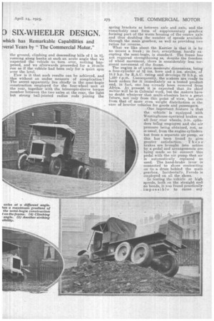
One day last week we were afforded an opportunity of making thorough tests with the new Kamer, and that these tests were drastic is clearly shown by some of our illustrations. We were given a free hand as to what the vehicle should be made to do, and we must confess that it far exceeded our expectations. Racked this way and that, with every axle at a different angle, and with a pair of rear wheels at one side having one wheel lifted perhaps a foot above the other, running at 20 m.p.h. over heaps of debris and through deep holes with both the front wheels bounding 8 ins. to 10 ins. off
the ground, climbing and descending hills of 1 in 31, running along banks at such an acute angle that we expected the vehicle to turn over, nothing happened, and we afterwards proceeded for a 10-mile run as if the vehicle had been only for a quiet spin over the level.
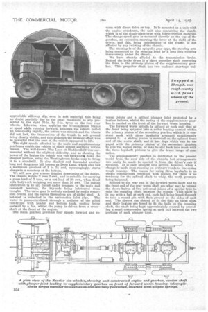
Er.ow is it that such results can be achieved, and this without an unduemeasure of complication? The secret apparently lies chiefly in the semi-bogie construction employed for the four-wheel unit at the rear, together with the telescopic-sleeve torque member between the two axles at the rear, the light but strong ball-jointed radius rods joining the spring brackets as between axle and_axle, and the remarkably neat form of . supplementary gearbox forming part of the worm housing of the centre axle and thus doubling the number of speeds available through the main gearbox, as well as providing two ratios for reverse.
What we like about the Karrier is that it is by no means a freak ; in fact, everything, hardly ex cepting the semi-bogie, is standard. The frame has not required strengthening as, despite the freedom of wheel movement, there is considerably less torsional movement of the frame.
The engine is of quite moderate dimensions, being a four-cylinder of 34 ins, bore and 5 ins, stroke, of
18.2 h.p. by R.A.C. rating and develops 22 b.h.p. at 1,250 r.p.in. Consequently, the makers are ready to book orders for it immediately as a tested 'product and, in fact, one has. already been received from
Africa. At present it is expected that its chief Int:tier will be in Colonial work, but the makers have
no doubt whatever that multi-wheelers have a great future, not only from this point of view, but also from that of more even weight distribution in the case of heavier vehicles for goods and passengers. . One important feature is that the vehicle ' is equipped with Westinghouse-operated brakes on
all four rear wheels, 5-in, cylinders being employee and the air
pressure being obtained, not, as is usual, from the engine cylinders but from a separate air pump, as this has been found to give greater satisfaction. These brakes are brought into action by a pedal and arrangements are being made so to connect this pedal with the air pump that air is automatically replaced as used. The hand-brake lever is connected to shoes contrasting on to a drum behind the main gearbox. Incidentafly, Ferodo is employed on all the shoes. In testing the vehicle at high speeds both on the straight and on bends, it was found practically• impossible to cause any
appreciable sideway slip, even in soft material, this being no doubt partially due to the great resistance to slip presented by the eight 33-in. by 5-in. tyres on the four rear wheels. Likewise, when applying the Westinghouse brakes at speed while running forward, although the vehicle pulled up remarkably rapidly, the action was smooth and the wheels did not lock, the impressions of the treads in soft ground being clearly visible, and this although the braking effect was so powerful that the rear of the vehicle appeared to lift.
The sight speeds afforded by the main and supplementary gearboxes enable the vehicle to climb almost anything within reason. The well-known Meg Lane at Huddersfield was surmounted without the slightest difficulty, and as showing the power of the brakes the vehicle was run tiaekwards down the -steepest portion, using the Westinghouse brake only to bring it to a standstill. It also climbed and descended another long and dangerous hill known as Deep Lane, which also has a maximum gradient of 1 in 31 and, encouragingly, starts alongside a cemetery at the bottom.
We will now give a more detailed description of the design. The chassis weighs 2 tons 2 cwt., and is suitable for carrying a gross load of 2 tons, or a net load of 30 cwt., when fitted with bo4work weighing not more than 10 cwt. The engine lubrication is by oil, forced under pressure to the main and camshaft bearings, the big-ends being lubricated from troughs. The valve gear is entirely enclosed by easily removable covers, and the valves themselves are of nickel steel. A hot-spot is embodied in the carburetter inlet pipe. The water is pump-circulated through a radiator of the gilled tube, type with header and bottom tank, cooling being assisted by a fan, whilst the pump is driven from a cross— shaft at the front of the engine.
The main gearbox provides four speeds forward and re verse with direct drive on top. It is mounted as a unit with the engine -erankcase, the unit also containing the clutch, which is of the single-plate type with fabric friction material. The change-speed gate is mounted directly on the top of the gearbox, an extension carrying the lever at the right of the driver, and this, being independent of the frame, is not affected by any twisting of the chassis.
The steering is of the epicyclic gear type, the steering arm being connected to the steering head by a long link running transversely under the chassis.
We have already alluded to the transmission brake. Behind the brake drum is a short propeller shaft conveying the drive to the primary pinion of the supplementary gearbox. This propeller shaft has two enclosed star-type uni
versal joints and a splined plunger joint protected by a leather bellows, whilst the easing of the supplementary gearbox is carried on the front of the forward worm housing.
The forward worm spindle is splined at each end, that at the front being spigoted into a roller bearing carried within the primary pinion of the secondary gearbox which is in constant mesh with three lay-shafts arranged equidistantly around it. A sliding pinion is mounted on the splined front end of the worm shaft, and it has dogs which can be engaged with the primary pinion of the secondary gearbox to give the higher ratios, or may be slid back into mesh with the three layshaft pinions to give the lower 'range of gear ratios.
The supplementary gearbox is controlled in the present model, from the near side of the chassis, but arrangements can easily be made to control it from thedriver's cab if required. It is only brought into service, however, when a change is made from running on ordinary roads to traversing rough country. The reason for using three layshafts is to obtain compactness combined with silence, for there is no tendency for the splined shaft to whip, the tooth presSure being balanced.
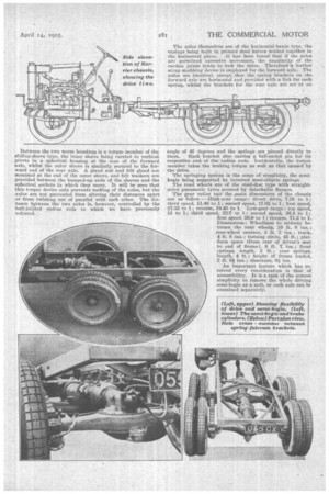
Splined to the rear end of the forward worm shaft and to the front end of the rear worm shaft are what may be termed the sleeve halves of two universal joints of a special type to take the coupling shaft between the worms. This shaft is in one with a ball at each end, each ball being bored through to take a round pin with flats ground at the sides of each end. The sleeves are slotted to fit the flats on these pins, and their insides 'are bored to fit the balls on the coupling shaft, the 'shaft being kept approximately central by providing a small compression spring at each en'] between the two portions of each plunger joint. Betiveen the two worm housings is a torque member of the sliding-sleeve type, the inner sleeve being carried in vertical Pivots in a spherical housing at the rear of the forward axle, whilst the outer sleeve is similarly secured to the forward end of the rear axle. A gland nut and felt gland are mounted at the end of the outer sleeve, and felt Washers are provided between the bumped-up ends of the sleeves and the spherical sockets in which they move.. It will be seen that this torque device only prevents rocking of the axles, but the axles are not prevented from altering their distances apart or from twisting out of parallel with each other. The distance between the two axles is, however, controlled by the ball-jointed radius rods to which we have previously referred. The axles themselves are of the horizontal-banjo type, the casings being built in pressed Steel halves welded together in the horizontal plane. It has been found that if the axles are permitted excessive mavement, "the atigulart(y of the cardan joints tends to lock the drive. Therefor4'ja leather strap snubbing device is employed for the forward axle. The axles are identical, except that the spring brackets on the forward axle are horizontal and provided with a link for each spring, whilst the brackets for the rear • axle are set at an angle of 45 degrees and the springs are pinned directly to them. Each bracket also carries a ball-ended pin for its respective end of the radius rods. Incidentally, the torque member takes the braking torque as well as that Caused by the drive, The springing system is the acme of simplicity, the semibogie being supported by inverted semi-elliptic springs.
The road wheels, are of the steel-disc type with straightsided pneumatic tyres secured by detachable flanges.
The gear ratios and the _main dimensions of the chassis are as follow :—High-gear range : direct drive, 7,25 to 1; third speed, 11.46 to 1; second speed, 17.62 to 1; first speed, 27.55 to 1; reverse, 34.45 to 1. Low-gear range : top speed, 15 to 1; third speed, 22.7 to 1; second speed, 36.4 to 1; first speed, 56.9 to 1; reverse, 71.2 to 1. Dimensions : Wheelbase to midway between the rear wheels, 10 ft. 6 ins.;
rear-wheel centres, 3 ft. 3 ; track, 4 ft. 8 ins.; turning circle, 45 ft.; platform space (from rear of driver's seat to end of frame), 8 ft. 7 ins.; front oprings, length, 3 ft.; rear springs, length, 4 ft.; height of frame loaded, 2 ft. 61 ins.; clearance, 9 ins.
An important feature which hag received every consideration is that of accessibility. It is a task of the utmost simplicity to remove the whole driving semi-bogie as a unit, or each axle can bt examined separately.