


Oil Engine with Flame Ignition
Page 34
If you've noticed an error in this article please click here to report it so we can fix it.
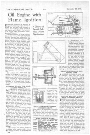
I NTENDED primarily for aircraft, a design of oil-burning engine shown in patent No. 524,092 is an attempt to reduce the weight per horse power of this type of power unit. The patentee is W. Harper, 1521, Drummond Street, Montreal, Canada.
The improvements lie in the combustion system which, although employing oil fuel, does not use compression for ignition, this function being carried out by the injection of a jet of flame. The drawing shows a single cylinder, part of a multi-cylindered flat-type engine. In operation, as the burnt charge is leaving via the exhaust valves (2) a new air-charge, compressed in the crankcase, enters via the pistoncontrolled ports (4). On the compression kroke, a charge of oil fuel is sprayed into the swirling air from an axially situated injector, not shown. Just before top dead centre, a spurt of flame issues from a passage (5) and causes ignition. This passage leads from a small auxiliary combustion chamber (1) which is provided with its own inlet valve, petrol injector, and sparking plug for the purpose of creating the flame jet. Petrol, although convenient as an auxiliary fuel, is not indispensable, mention being made of the Standard Oil Company's safety fuel.
The patent also deals with the method of charging the crankcase with pressure air; this is done with the assistance of high-pressure exhaust gas, which is drawn off $rom a special small exhaust valve (3). The last-named is arranged to be opened only during a short period when the exhaust pressure is high.
AUTOMATIC CLUTCH FOR REARENGINED VEHICLES ACCORDING to patent No. 523,954, the clutch of a rear-engined ous often suffers more misuse than one in a vehicle with the engine at the front, the reason being that the driver cannat hear his engine so clearly.
The patentee, Borg-Warner Corp., Chicago, U.S.A., discloses a centrifugal control unit for use on such vehicles. The drawing shows a section of the device, which is intended to he run at about twice engine speed, say, from the generator spindle.
The unit operates the existing clutch in accordance with the speed of the engine. The outer end of the lever (1) is linked to the clutch lever on the • engine, whilst the inner end is controlled by a sliding rod (2) whose! position is governed by the weighted: bell-cranks (3). At idling speeds, the springs (4) are powerful enough to pull the weights into the dotted-line position, but as the speed rises, the springs (4) are overcome by centrifugal force, and the main clutch is allowed to engage.
A lost-motion link enables the driver to retain pedal control, and a means for locking the lever (1) permits of the NOVEL COMBUSTION-CHAMBER ATOMIZING MEANS
710 obtain the maximum throttling 1 effect in the neck of a pre-combustion chamber, and yet to retain a relatively large diameter, is the object of a design shown in patent No.. 523,554,
by Daimler-Benz A.G., Stuttgart, Germany.
One of several schemes . is shown in the drawing; the same principle, however underlies all. The ; precombustion chamber ; is connected to the cylinder space by means of a passage consisting of a. number of spaced washers (1) the bores of which are larger than is usual with a plain bore. The annular spaces between the washers create eddies which promote atomization of the fuel, whilst the large central passage enables ample fuel to reach the cylinder space when starting—a desirable feature.
IMPROVED HYDRAULIC END. TIPPING GEAR
PIA SCHEME to abolish the usual gap between body and cab which exists where an hydraulic tipping cylinder has to be housed is shown in patent No. 524,020 by M. Edwards, Pilot Works, Manchester Road, Bolton.
The drawing shows the body in both positions, and it will be seen that the ram is housed in a cavity in the front part of the body. The cavity is V-shaped in plan, and contains an angle-iron framework to take the thrust of the ram. An additional advantage is that foreign matter, such as sand,1 cannot fall upon the ram when loading. i
ELECTRIC HEATING SYSTEM • WITH AUTOMATIC SWITCH
THERE is no doubt that electricity ' is the most convenient medium for vehicle heating, although somewhat ' more expensive to run than the system employing hot air from the radiator. An improved electric system forms the subject of patent No. 523,861 which comes from C.A.V., Ltd., and others, Warple Way, London, W.3.
In this scheme, it is proposed to employ a special engine-driven generator and storage cells, although the usual lighting dynamo, in enlarged form, may be used if desired. Tha heating elements are controlled by a pair of switches, one manual and one automatic. The automatic switch ensures that the load is given to the generator so soon as it commences to run, the storage cells being used only when standing. The auto-switch also reduces the current to within practical I limits When the cells are in use.