


Saurer Springing Modification
Page 54
If you've noticed an error in this article please click here to report it so we can fix it.
A Resume of Recently Published Patent Specifications
IN vehicles of the twin'. rear-axle type, in which only one axle is driven, it is often desirable to increase the load on the
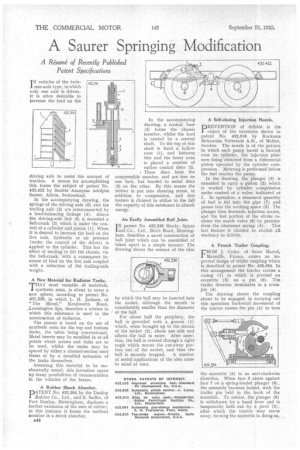
driving axle to assist the amount of traction. A means for accomplishing this forms the subject of patent No. 432,422 by Societ6 Anonyme Adolphe Saurer, Arbon, Switzerland.
In the accompanying drawing, the springs of the driving axle (6) and the trailing axle (3) are interconnected by a load-balancing linkage (4). Above the driving-axle link (5) is mounted a bell-crank (2) which is under the control of a cylinder and piston (1). When it is desired to increase the load on the live axle, hydraulic or air pressure (under the control of the driver) is applied to the cylinder. This has the effect of tending to lift the chassis, via the bell-crank, with a consequent increase of load on the live axle coupled -with a reduction of the trailing-axle weight.
A New Material for Radiator Tanks.
THAT most versatile of materials, synthetic resin, is about to enter a new sphere, according to patent No. 431,520, in which L. H. Jackson, of "The Hirsel," Kenilworth Road; ..Leamington Spa, describes a scheme in which this substance is used in the construction of radiators.
The patent is based on the use of synthetic resin for the top and bottom tanks, the tubes being conventional. Metal inserts may be moulded in at all points where screws and bolts are to be used, whilst the tanks may be spaced by either a channel-section steel frame or by a moulded extension of the tanks themselves.
Assuming this material to be mechanically sound, this invention opens Aft many possibilities of ornamentation in the vehicles of the future.
A Rubber Shock Absorber. DATENT No. 432,304 by the Dunlop 1 Rubber Co., Ltd., and S. Sadler, of Fort Dunlop, Birmingham, discloses a. further extension of the uses of rubber; in this instance it forms the resilient member in a shock absorber.
B44 In the accompanying drawing, a conical base (4) forms the chassis member, whilst the load is carried by a central shaft. To the top of this shaft is fixed a hollow cone (1), and between this and the lower cone is • placed a number of rubber conical discs (2).
7 These discs form the compressible member, and are free on one face, but bonded to metal discs (3) on the other. By this means the rubber is put into shearing stress, in addition to compression, and this feature is claimed to utilize to the full the capacity of this substance to absorb energy.
An Easily Assembled Bail Joint,
I N patent No, 432,336 Hardy, Spicer
and Co., Ltd., Birch Road, Birmingham, describes a novel construction of ball joint which can be assembled or taken apart in a simple manner. The drawing shows the essence of the idea by which the ball may be inserted into the socket, although the mouth is considerably smaller than the diameter of the ball.
For about half the periphery, the ball is provided with a groove (1) which, when brought up to the mouth of the socket (2), clears one side and allows the ball to enter. After insertion, the ball is rotated through a right angle which moves the cut-away portion out of the socket, and thus the ball is securely trapped. A number of useful applications of the idea come to mind at once. A Self-closing Injection Nozzle.
DREVENTION of dribble is the 1 object of the invention shown in patent No. 932,518. by Kockums Mekaniska Verkstads A.B., of Malmii, Sweden. The nozzle is of the pattern in which each pump barrel is located over its cylinder, the injection pressure being obtained from a differential piston operated by the cylinder compression. Metering is performed before the fuel reaches the pump.
In the drawing, the plunger (3) is extended to carry a piston (2) which is worked by cylinder compression under; control of a valve, indicatedat 1. In operation, a measured quantity of fuel is fed into the pipe (7) and passes into the working.space (5): The plunger then descends, injection occurs, ' and the last portion of the stroke recloses the nozzle valve (6) by pressure from the abutment spring (4)-.-This last feature is claimed to abolish all tendency to dribble.
A French Trailer Coupling.
FROM J. Coder, of Saint Marcel, Marseille, France, comes an improved design of trailer coupling 'which is described in patent No. 432,554. In this arrangement the tractor carries a casing (I) in which is pivoted an eccentric (5) on a pin (6). The trailer drawbar terminates in a crosspin (4).
The drawing shows the coupling about to be engaged; in carrying out this operation backward ,movement of the tractor causes the pin (9) to turn
the eccentric (5) in an anti-clockwise direction. When face 3 abuts against face 7 on a spring-loaded plunger (8), the assembly becomes locked, with the trailer pin held in the hook of the eccentric. To release, the plunger (8) is withdrawn by a hand lever and is temporarily held out by a pawl (2), after which the tractor may move away, turning the eccentric in doing so,