


Body for Chassis-frameless Coach
Page 36
If you've noticed an error in this article please click here to report it so we can fix it.
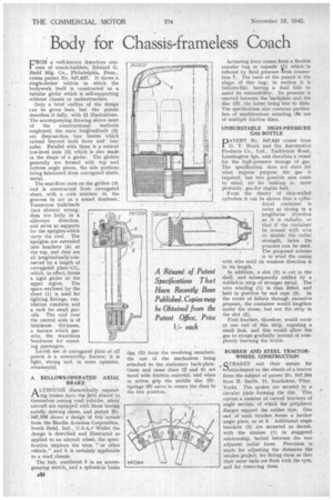
FROM a well-known American concern of coach-builders, Edward G. Budd Mfg. Co., Philadelphia, Penn., comes patent No. 547,627. It shows a single-decker vehicle in which the bodywork itself is constructed as a tubular girder which is self-supporting without chassis or understructure.
Only a brief outline of the design can be given here, but the patent describes it fully, with 21 illustrations. The accompanying drawing shows most of the constructional methods employed; the main longitudinals (3) are deep-section box beams which extend beyond both front and rear axles. Parallel with these is a central low-level aisle (2) which is also made in the shape of a girder. The girders generally are formed with top and bottom angle pieces, the side portions being fabricated from corrugated sheetmetal.
The seat-floor rests on the girders (3) and is constructed from corrugated sheet, with a cork mixture in. the grooves to act as a sound deadener. Transverse bulkheads (not shown) strengthen the body in a sideways direction, and serve as supports for the uprights which carry the roof. The uprights are extended into brackets (4) at the top, and they are all longitudinally connected by a length of corrugated plate •(1), which, in effect, forms a rigid girder at the upper region. The space enclosed by the sheet (1) is used for lighting fittings, ventilation conduits and a rack for small parcels. The roof over the central aisle is of minimum thickness, a feature which permits the maximum headroom for standing passengers.
Lavish use of corrugated plate at all points is a noteworthy feature; it is light, strong and, in some opinions, ornamental.
A BELLOWS-OPERATED AXIAL BRAKE A LTHOUGII diametrically expand
ing brakes have the field almost to themselves among road vehicles, many aircraft are equipped with those having axially moving shoes, and patent No. 547,336 shows a design' of this 'nature from the Bendix Aviation Corporation, South Bend, Ind. U.S.A.,. Whilst the design is described and illustrated as applied to an aircraft wheel, the specification employs the term "or other vehicle," and it is certainly applicable to a road chassis.
The hub, numbered 3 in an accompanying sketch, and a splined-in brake
disc (5) form the revolving members, the rest of the mechanism being attached to the stationary back-plate. Outer and inner discs (2 and 4) are faced with friction material, and when in action grip the middle disc (5). Springs. (6) serve to return the discs to the free position.
Actuating force comes from.a flexible annular bag or capsule (.1) which, is inflated by fluid pressure From connection 7. The basis of the patent is the shape of this bag.; in section it is bellows-like, having a dual fold to assist its extensibility. Its pressure is exerted between the backplate and the disc (2), the latter being free to slide. The specification also contains particulars of modifications entailing the use of multiple friction discs.
UNBURSTABLE HIGH-PRESSURE GAS BOTTLE
pATENT No. 547,642 comes from D. T. Brock and the Automotive Products Co., Ltd., Tachbrook Road. Leamington Spa, and describes a vessel for the high-pressure storage of gas. The specification does not state for what express purpose the gas is required, but two possible uses come to mind, air for braking or, more probably, gas for engine fuel.
From the theory of thin-walled cylinders it can be shown that a cylindrical container is twice as strong in a lengthwise direction as it is radially, so that if the container be wound with wire to double the radial strength, twice the pressure can be used. Theproposed scheme is to wind the casing with wire until its weakest direction is in its length.
In addition, a slot (2) is cut in the shell, and subsequently refilled by a welded-in strip of stronger metal. The wire winding (1) is then fitted, and held in Position by end caps (9). In the event of failure through excessive pressure, the container would lengthen under the stress, but not the strip in the slot (2).
First fracture, therefore, would occur at one end of this strip, exposing a small leak, and this would allow the gas to escape gradually instead of completely bursting the bottle.
RUBBER AND STEEL TRACTOR. WHEEL CONSTRUCTION .1{ QTRAKES and their means for ihiattachment to the wheels of a tractor form the subject of patent No. 547,264 from R. Smith, 21, Southdene, Filey, Yorks. The spokes are secured to a circular plate forming the rim. This carries a number of curved brackets of angle section, of which the peripheral flanges support the rubber tyre. One end of each bracket forms a further angle piece, as at 3. Additional angle brackets (2) are mounted as shown, with the strakes (1) in staggered relationship, bolted between the two adjacent radial faces. Provision is made for adjusting the distances the strakes project, for fitting them so that their outer ends are flush with the tyre, and for removing them.