 1
1 2
2 3
3 4
4 5
5 6
6 7
7 8
8 9
9 10
10 11
11 12
12 13
13 14
14 15
15 16
16 17
17 18
18 19
19 20
20 21
21 22
22 23
23 24
24 25
25 26
26 27
27 28
28 29
29 30
30 31
31 32
32 33
33 34
34 35
35 36
36 37
37 38
38 39
39 40
40 41
41 42
42 43
43 44
44 45
45 46
46 47
47 48
48 49
49 50
50 51
51 52
52 53
53 54
54 55
55 56
56 57
57 58
58 59
59 60
60 61
61 62
62 63
63 64
64 65
65 66
66 67
67 68
68 69
69 70
70 71
71 72
72 73
73 74
74 75
75 76
76 77
77 78
78 79
79 80
80 81
81 82
82 83
83 84
84 85
85 86
86 87
87 88
88 89
89 90
90 91
91 92
92 93
93 94
94 95
95 96
96 97
97 98
98 99
99 100
100 101
101 102
102 103
103 104
104 105
105 106
106 107
107 108
108 109
109 110
110 111
111 112
112 113
113 114
114 115
115 116
116 117
117 118
118 119
119 120
120 121
121 122
122 123
123 124
124 125
125 126
126 127
127 128
128 129
129 130
130 131
131 132
132 133
133 134
134 135
135 136
136 137
137 138
138 139
139 140
140 141
141 142
142 143
143 144
144 145
145 146
146 147
147 148
148 149
149 150
150 151
151 152
152 153
153 154
154 155
155 156
156 157
157 158
158 159
159 160
160 161
161 162
162 163
163 164
164 165
165 166
166 167
167 168
168 Promising Epicyclic Gearbox
Page 93
If you've noticed an error in this article please click here to report it so we can fix it.
with novel hydraulic control
A New Transmission which Enables a Vehicle to be Controlled by Only Two Pedals and Affords a Very Easy Gear Change
WE have recently had the opportunity of testing, on the road, a new transmission, produced by Propello Inventions, Ltd., which embodies many interesting features. Although no new principle is involved in its construction, the performance is such as to command respect.
The transmission which we tried was fitted to a 10 h.p. car, but is of a form which would be quite suitable for light commercial vehicles. It is also being developed in larger, sizes and the main featureg have been evolved and tested over a period of several years. One of The experimental gearboxes has 50,000 miles on the road and another, of a slightly different type, now has 40,000 miles to its credit.
The transmission comprises a fluid coupling, similar in action to the wellknown Daimler Fluid Flywheel but of somewhat different design, and an epicyclic gearbox controlled from a gear lever mounted on the steering column. The fluid coupling gives an automatic pick-up from a standstill and the gearchange mechanism is. expressly arranged to operate smoothly without breaking the drive between engine and gearbox, or between gearbox and propellet shaft. Consequently, no clutch (or clutch pedal) is needed, so that' the driver can operate the vehicle using the right foot for the accelerator and the left foot for the brake,
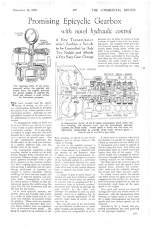
As in most epicyclic' Systems, the various gears are brought into action by a series of brake bands and by two small cone clutches, all mounted within the gearbox. These units are operated hydraulically, the necessary fluid, pressure being derived from an ingenious form of eccentric-driven pump. The pump is coupled to an extension of the
fluid coupling, as shown in the layout diagram, and is driven whenever the engine is turning.
So soon as the requisite pressure is built up, the working end of the pump 'lever comes almost to a standstill and the motion of the eccentric drive is taken up in a spring-loaded fulcrum block. Another important feature of the hydraulic system is a restriction which is introduced between the pump and a rotary valve ; this valve controls ports which lead to the various plungers used to operate the brake bands and clutches.
A change of gear is made simply by moving the gear lever (which is coupled to the rotary valve) from one position to another and is accompanied by a momentary drop in hydraulic pressure. The pump then deliver§ oil through the port selected by the valve and, although the pressure is built up quite quickly, there is a sufficient lag, to ensure the smooth application of the selected brake band or clutch, as the case may oe.
The epicyclic part of the mechanism has been cleverly worked out to ensure quiet running and durability. The epicyclic trains are compounded in an in genious way in order to obtain a large number of speed ratios with few working parts. An example which provides five forward speeds and a reverse, the fourth speed being direct whilst the fifth is an overdrive, is shown in diagrammatic form, There are four epicyclic trains, controlled by brake bands, and there are two cdne clutches. Incidentally, the brake bands are duplicated on each drum to give a balanced action and are self-adjusting for wear.
A direct drive is obtained when both the clutches (A and B) are engaged. To obtain an overdrive the first clutch (A) is disengaged and a brake is applied to the first epicyclic train. This drives the intermediate shaft at a speed somewhat higher than that of the engine. • The second clutch (B) is engaged to convey the power through the remaining trains (turning solidly) to the-tailshaft.
• For third speed the overdrive gear is used, as before, and the speed is then stepped down, between the intermediate shaft and the tailshaft, through the second and third epicyclic trains.
TO obtain second speed, the second and third trains are again used but, by engaging the first clutch (A), the overdrive is rendered inoperative so that the intermediate shaft. turns at the same speed as the engine.
First speed and reverse are obtained through the third and fourth trains, respectively, with the intermediate shaft running at engine speed in each case. By a slight rearrangement six forward speeds and two reverse speeds can be obtained.
Invented by Mr, J. Yoxail, this promising transmission has been patented in the principal countries.