


Device for Mixing Water with Petrol
Page 62
If you've noticed an error in this article please click here to report it so we can fix it.
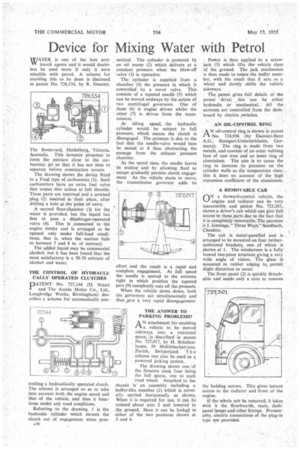
WATER is one of the best antiVV knock agents and it would doubtless be used more if only it were miscible with petrol. A scheme for enabling this to be done is disclosed in patent No. 726,534, by R. Dunster, The Boulevard, Heidelberg, Victoria, Australia. This inventor proposes to form the mixture close to the carburetter jet so that it has not time to separate before atomization occurs.
The drawing shows the device fitted to a Ford type of carburetter. (1). Such carburetters have an extra fuel valve that comes into action at full throttle. These parts are removed and a screwed plug (2) inserted in their place, after drilling a hole g the point of entry.
A second float-chamber (3) for the water is provided, but the liquid has first to pass a diaphragm-operated valve (4). This is connected to the engine intake and is arranged to be opened only under full-load conditions, that is, when the suction falls to between 5 and 8 in. of mercury.
The added liquid may be commercial alcohol, but it has been found that the most satisfactory is a 50-50 mixture of alcohol and water.
THE CONTROL OF HYDRAULICALLY OPERATED CLUTCHES
PATENT No. 727,144 (D. Stuart and The Austin Motor Co., Ltd., Longbridgc Works, Birmingham) describes a scheme for automatically con
trolling a hydraulically operated clutch. The scheme is arranged so as to take into account both the engine speed and 'that of the vehicle, and thus it functions under any road conditions.
Referring to the drawing, 1 is the hydraulic cylinder which thrusts the clutch out of engagement when ores surized. The cylinder is powered by an oil pump (2) which delivers at a constant pressure when the blow-off valve (3) is operative.
The cylinder is supplied from a chamber (4) the pressure in which is controlled by a novel valve. This consists of a tapered needle (5) which can be moved endways by the action of two centrifugal governors. One of these (6) is engine driven whilst the other (7) is driven from the transmission.
At idling speed, the hydraulic cylinder would be subject to full pressure, which means the clutch is disengaged. The pressure is due to the fact that the needle-valve would then be seated at 8 thus obstructing the passage from the exhaust pressure chamber.
As the speed rises, the needle leaves its seating and by allowing fluid to escape gradually permits clutch engagement. As the vehicle starts to move, the transmission governor adds its effort and the result is a rapid and complete engagement. At full speed the needle is moved to the extreme right in which position the tapered part (9) completely cuts off the pressure.
When the vehicle slows down, both the governors act simultaneously and thus ,givc a very rapid disengagement.
THE ANSWER TO PARKING PROBLEMS?
AN attachment for enabling a vehicle to be moved sideways into a restricted space, is described in patent No. 727,017, by H. Schellenbaum, 59 Muhlebachstrasse, Zurich, Switzerland. T h e scheme can also be used as a powered jacking system.
The drawing shows one of the fitments used, four being the full quota, one to each road wheel. Attached to the chass's is an assembly including a buffer-like member (1) which is normally carried horizontally as shown. When it is required for use, it can be rotated about axis 2 and lowered to the ground.. Here it can be locked in either of the two positions shown at 3 and 4. Power is then applied to a screwjack (5) which lifts the vehicle clear of the ground. The jack mechanism is then made to rotate the buffer member, with the result that it acts as a wheel and slowly shifts the vehicle sideways.
The patent gives full details of -tke power drive; this can be either hydraulic or mechanical. All the motions are controlled from the dashboard by electric switches.
AN OIL-CONTROL RING
AN oil-control ring is shown in patent No. 724,936 (by Daimler-Benz A.G., Stuttgart-Untertilrkheim, Germany). The ring is made from two metals, and consists of an outer rubbing face of cast iron and an inner ring of aluminium. The aim is to cause the ring to increase its pressure on the cylinder walls as the temperature rises; this it does on account of the high expansion coefficient of the aluminium.
A REMOVABLE CAB
ON a forward-control vehicle, the engine and radiator can be very inaccessible and patent No. 725,301, shows a driver's cab which can give full access to these parts due to the fact that it is completely removable. The patentee is J. Jennings, "Three Ways," Sandbach, Cheshire.
The cab is metal-panelled and is arranged to be mounted on four rubbercushioned brackets, one of which is shown at 1. The windscreen is a fully bowed two-piece structure giving a very wide angle of vision. The glass is mounted in rubber edging to permit slight distortion to occur.
The front panel (2) is quickly detachable and needs only a coin to remove the holding screws. This gives instant access to the radiator and front of the engine.
If the whole cab be removed, it takes with it the floorboards, seats, dashpanel lamps and other fittings. Presumably, electric connections of the plug-in type Are provided.