


Five Ratios With Only Four Gear-trains
Page 26
If you've noticed an error in this article please click here to report it so we can fix it.
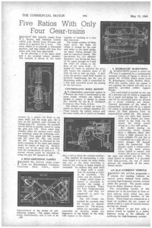
PATENT NO. 616,474, comes from J. Naylor, and Atkinson Lorries (1933), Ltd., Marsh Lane, Preston, and refers to a gearbox for a lorry. The main object is to provide a shortened gearbox, and one which will give five ratios with only four gear-trains.
In the thawing, 1 is the kriput shaft and 2 the co-axial output member. The layshaft is driven in the usual manner by a pinion (A) fixed to the input shaft, but the large gear (B) is free on the layshaft until clutched by sliding dogs (3). Actually, the layshaft can be driven at another speed by using the gear pair CD. Three other dogclutches select the various ratios which arc obtained, using the following combinations: First speed AB, HK, second AB, EF, third DC, HK, and fourth DC, EF. Top gear is obtained by the direct couplingof the input and output shafts by means of dogs (3). Reverse makes use of the gears AB and FG, with the interposition of pinion 4. A second reverse could be obtained by using the pair DC instead of AB.
A SELF-ADJUSTING TAPPET DATENT No. 615,341, which comes from the Weatherbead Company, Cleveland. Ohio, U.S.A., shows improvements in the design of selfadjusting tappets. The tappet shown works hydraulically, and is said to be A38 capable of working to a very fine clearance.
The tappet consists of three main parts, the body (1) which is moved by the cam and slides in the usual guide, an upper sliding plunger (2) and an innermost piston. The last-named has two effective diameters, one fitting the bore of the upper plunger at 3 and the other (4) sliding in the bore of the main body. A spring (5) tends to separate the parts, and causes the topmost space to fill with oil and so take up slack. A ballvalve (6) permits rapid fluid transfer to facilitate lengthening, but the rate of shortening under load is controlled by a fine leak scratched across the seating of the ball-valve.
CONTROLLING BODY HEIGHT
AN independent suspension system in which the body is maintained at the same height whether the vehicle be loaded or empty, is shown in patent No. 616,299, by the B. F. Goodrich Company, New York, U.S.A.
The wheels are carried on arms (1) which are fixed to tubular members (2). These contain the rubber sleeves and the inner shafts, all of which are bonded into a unit to form the resilient member.
The method of maintaining a constant height is to rotate the inner shafts one way or the other according to whether the vehicle is being loaded or unloaded. To achieve this, each shaft is fitted with a crankarm (3) carrying a roller at its extremity. The roller can be moved by a wedge which raises or lowers it according to whether the wedge is pulled or pushed. There are four wedge-carrying rods (4), and they are connected in pairs by bell-cranks (5).
The bell-cranks are worked by screwed rods (6) rotated by electric motors (7). The motors, which are reversible, are controlled by switches which are responsive to the height of the body with respect to the chassis. A HYDRAULIC SUSPENSION
ASUSPENSION system in which the load is supported by a continuously pumped column of liquid, is shown i in patent No. 615,874, which comes from W. Kennington, Cordic, Radlett, Herts. With this system, when the engine is not running, the vehicle will sink on to specially provided rubber support blocks.
The road-wheel is carried on the end of a pivoted arm (1) which is supported by a small leaf-spring (2). Bracket 3 and all its associated parts are pivoted on a frame trunnion, not shown. Upward movement of the wheel is transmitted via an arm (4) to a piston (5) which is maintained in the position shown by fluid pressure from an engine-driven pump (6). The proportions are such that normal slow road shocks are trans mined to the body via the piston, the whole system acting as a very stiff spring.
But shocks having an acceleration above normal havea different effect; they create a high pressure in a small cylinder (7) and this is transmitted via a pipe (8) to a small plunger (9) housed . inside the piston-rod. The plunger opens a release-valve
(10) in the main piston;
allows liquid to escape, and enables the piston to move to the right and absorb the blow. The small piston in cylinder 7 is provided with leak-grooves, the size of which governs the magnitude of the transmitted shocks.
AN H.-F.-CURRENT VEHICLE
PATENT NO. 615,916, propounds a scheme for running vehicles on electric power induced from cables, carrying high-frequency current, located under the ground. The patent comes from G. Babat, Moscow, Russia.
The outstanding novelty of this scheme lies in the provision of three or four pick-up loops which may also form constructional members of the frame. These loops are connected to a bank of rectifiers, the d.c. output of which is fed to a pair of traction motors driving the wheels.
It is difficult to see how such a system would he applied to a public highway owing to the difficulty of confining the high-frequency current.