 1
1 2
2 3
3 4
4 5
5 6
6 7
7 8
8 9
9 10
10 11
11 12
12 13
13 14
14 15
15 16
16 17
17 18
18 19
19 20
20 21
21 22
22 23
23 24
24 25
25 26
26 27
27 28
28 29
29 30
30 31
31 32
32 33
33 34
34 35
35 36
36 37
37 38
38 39
39 40
40 41
41 42
42 43
43 44
44 45
45 46
46 47
47 48
48 49
49 50
50 51
51 52
52 53
53 54
54 55
55 56
56 57
57 58
58 59
59 60
60 61
61 62
62 63
63 64
64 65
65 66
66 67
67 68
68 69
69 70
70 71
71 72
72 73
73 74
74 75
75 76
76 77
77 78
78 79
79 80
80 81
81 82
82 83
83 84
84 85
85 86
86 87
87 88
88 89
89 90
90 91
91 92
92 93
93 94
94 95
95 96
96 97
97 98
98 99
99 100
100 101
101 102
102 103
103 104
104 105
105 106
106 107
107 108
108 109
109 110
110 111
111 112
112 113
113 114
114 115
115 116
116 117
117 118
118 119
119 120
120 121
121 122
122 123
123 124
124 125
125 126
126 127
127 128
128 129
129 130
130 131
131 132
132 133
133 134
134 135
135 136
136 Hydrostatic Drive for Universal
Page 80
If you've noticed an error in this article please click here to report it so we can fix it.
Application P A novel transmission w
ith M.I.R.A. connections
DETAILS of the twin-shunt hydrostatic transmission mentioned by Dr. J. G. Giles, consulting engineer and ex-deputy director of the Motor Industry Research Association, at a meeting of the Institute of Road Transport Engineers, Midland Centre, recently (reported in last week's issue of The Commercial Motor) give promise that the unit could be produced at a reasonable cost and that it could be built in capacities covering the majority of commercial-vehicle requirements. In his paper on automatic transmissions, Dr. Giks pointed out that the heavy goods vehicle operated for much of its time at low b.m.e.p.s, which wasted fuel, and that a stepless transmission could reduce consumption, compared with a conventional gearbox, if a comparable or near-comparable efficiency could be obtained.
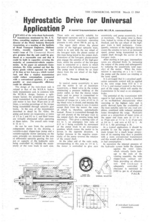
The design. of the twin-shunt unit is related to that of the M.I.R.A. hydrostatic transmission and, in common with the M.I.R.A. design„ features a splittorque layout; the proportion of power input transmitted by the hydraulic-pump and motor is less than 50 per cent at all times, a varying' percentage ,.of the torque being transmitted through epicyclic gear -trains. In the case of the transmission described in detail by Dr. Giles, the pump and motor are inoperative at ratios of 1-5 to I and 0P2 to 1, and fluid losses
, are virtually eliminated when, operating . , at these ratios. The overall ratio range
is 12 .to I.•. :• , As can be seen from the sectioned components shown in the drawing, a variable output slipper type pump and a variable-capacity motor operating on the same. principle are mounted,on the axis of differential epicyclic gearing, the ,ontput pr capacity of the hydraulic units being controlled by varying the eccentricifY of the vane track, in each case.
These units are specially suitable for high-speed operation and it is significant that the normal maximum operating pressure is only about 500 lb.. per sq. in.
The input shaft drives the planet carrier of the high-gear epicyclic train, which is in unit with the sun wheel of .the low-gear train, the planet carrier of this train being keyed to the output shaft. Extensions of the low-gear, planet-carrier pins engage the annulus of the high-gear train, whilst the •annulus of the low4ear train is connected to a sleeve to which the rotor of the hydraulic motor is keyed. The pump rotor is driven by an inner sleeve from the sun wheel of the highgear train.
No Pressure Build-up.
In neutral, pump eccentricity, is zero and the motor is set at maximum eccentricity, a bleed valve in the System eliminating a pressure build-up, at the motor outlet, so that the sleeves •rotate freely and no power is _ transmitted' to the output' shaft. : To initiate the trans!. mission of torque (at a ratio of in to 1) the bleed valve:is closed, and because. the eccentricity of the pump is 'zero it cannot -. accept fluid from the motor, the rotor. of , which .is, • therefore, , antomatically. locked: Power. is transmitted through the sun and planets of the low-gear train to the output shaft, the annulus being held stationary. This gives a starting ratio of 0.2 to 1, an emergency low : ratio of ,O.:15 to I being available by. movement of the pump track to an over-centre .position, which causes the motor to be driven . in the opposite directionA further increase in the negative eccentricity of the pump reverses the rotation of the output shaft.', At At the other ,end of the ratio scale, corresponding. in this case .to 1:5 to. 1, the motor is controlled to give zero eccentricity and pump eccentricity, is set at maximum. The pump rotor is, therefore, locked by _virtue of the outlet being blocked, and the sun _wheel of the highgear train is held stationary. Consequently, rotation of the high-gear carrier causes the annulus to turn at an increased speed, power being transmitted to the output shaft through the carrier of the low-gear train.
After starting in low gear, intermediate ratios are obtained firstly by increasing the output of the pump and•subsequently by reducing the eccentricity (and capacity) of the motor. When the transmission is operating on a I to 1 ratio, the pump and the motor are rotating at
the same speed. , .
It is envisaged that in a practical application automatic control will be .applied
to the ratio range from 055 to to 1-5 to 1, and manual control to the lower part of the range, which will enable the . transmission to be used as an emergency brake. .
The potential of the transmission With regard to fuel saving is partly a function of its n(3-fluid:logs characteristic when
• opetating in the highest, ratio and is partly derived; ftoin• the availability. of the most suitable ratio for any road condition. combined with reduced pumping losses throughout the range. Hydraulic power as a proportion of input varies at the upper end from zero at 125 toI; to 19 per cent at 12 to 1; to 45 per cent at 0-6. to I,. and zero at 0-2 to 1. At
0•15 to 1, the percentage is 36. .
-In a typical application, -it should be possible to .run the engine near maximuin torque for a much larger proportion of its running time than is possible with a more conventional transmission and this would afford a further reduction in fuel consumption.
In operation the internal pressure of the hydraulic system holds the slippers
against the rotor vanes, which virtually limits leakage to the ends of the rotating assembly, the wide slipper-track contact stir-faces providing an effective seal. End leakage is adequately controlled if clearance is restricted to 0001 in, per in. of diameter.
P.A.C.B. •