 1
1 2
2 3
3 4
4 5
5 6
6 7
7 8
8 9
9 10
10 11
11 12
12 13
13 14
14 15
15 16
16 17
17 18
18 19
19 20
20 21
21 22
22 23
23 24
24 25
25 26
26 27
27 28
28 29
29 30
30 31
31 32
32 33
33 34
34 35
35 36
36 37
37 38
38 39
39 40
40 41
41 42
42 43
43 44
44 45
45 46
46 47
47 48
48 49
49 50
50 51
51 52
52 53
53 54
54 55
55 56
56 57
57 58
58 59
59 60
60 61
61 62
62 63
63 64
64 65
65 66
66 67
67 68
68 69
69 70
70 71
71 72
72 73
73 74
74 75
75 76
76 77
77 78
78 79
79 80
80 81
81 82
82 83
83 84
84 85
85 86
86 87
87 88
88 89
89 90
90 91
91 92
92 93
93 94
94 95
95 96
96 97
97 98
98 99
99 100
100 101
101 102
102 103
103 104
104 105
105 106
106 107
107 108
108 109
109 110
110 111
111 112
112 113
113 114
114 115
115 116
116 117
117 118
118 119
119 120
120 121
121 122
122 123
123 124
124 125
125 126
126 127
127 128
128 129
129 130
130 131
131 132
132 133
133 134
134 135
135 136
136 137
137 138
138 139
139 140
140 141
141 142
142 143
143 144
144 145
145 146
146 147
147 148
148 149
149 150
150 151
151 152
152 153
153 154
154 155
155 156
156 157
157 158
158 159
159 160
160 161
161 162
162 163
163 164
164 165
165 166
166 167
167 168
168 169
169 170
170 171
171 172
172 173
173 174
174 175
175 176
176 177
177 178
178 179
179 180
180 Two-speed Differential
Page 136
If you've noticed an error in this article please click here to report it so we can fix it.
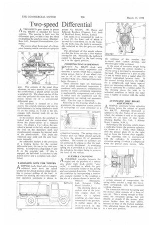
ATWO-SPEED gear shown in patent No. 808,543 is intended for heavy vehicles. The gearing is built into the differential gear, so that it has the effect of doubling the gearbox ratios. (DaimlerBenz A.G., Stuttgart-Unterturkheim, Germany.)
The crown-wheel forms part of a threepiece housing which contains an epicyclic gear. This consists of the usual three elements, an outer annulus (1) cut inside the crown-wheel, a planet carrier (2) and a sunwheel (3). The planet-carrier. of this unit also performs the same duty for the planet bevels (4) of a conventional differential gear.
The sunwheel is formed on a free sleeve; this extends sideways and can be held stationary by being clutched to teeth (5) on the casing, or, if slid to the left, engages with internal teeth (6) on the planet-carrier.
In the position shown, the sunwheel is locked and the crown-wheel therefore drives the planet-carrier at a reduced ratio. To obtain a 1 to 1 drive, the sunwheel is moved to the left, which releases the lock on. the. stationary teeth and simultaneously engages the internal teeth of the planet-carrier. This locks, the reduction gear, solid and the axle functions normally.
An additional feature is the provision of a locking device for the normal differential gear, for use in icy road conditions. It comprises a dog-clutch (7 and 8) on the opposite side. If this is engaged, the half-shaft is clutched to the planet-carrier and a Complete lock established.
TAILBOARD LOCK FOR TIPPERS
ATIPPING body fitted with a hanging tailboard must have the board latched in the closed position when travelling to prevent spillage of the load. A scheme for making this small but important operation automatic is shown in
patent No. 807,104. (W. Hayes and Edwards Brothers (Tippers), Ltd., both of Bradford Street, Bolton, Lancs.) The latch (1) is connected by rods to a lever (2), the lower end of which is located in a cam-block (3) on the frame. As the body rises, the latch is automatically unlocked so that the gate can swing open.
The advantages of this simple scheme are that the driver can tip a load without leaving his cab. Moreover, the tailboard cannot be damaged by the load resting on it in the tipped position.
COMPENSATING SUSPENSION
PATENT No. 808,673 deals with independent wheel suspension and -describes a system which has a compensating action, that is, if one wheel rises one or all of the others tend to fall. (Daimler-Benz A.G., Stuttgart-Unterturkheim, Germany.)
Three different types are mentioned, one in which mechanical suspension is combined with pneumatic compensation, another in which a pneumatic suspension is mechanically compensated and a third in which both the suspension and the compensation are carried out pneumatically, The first type is illustrated.
Referring to the drawing, which is diagrammatic, the suspension system consists of coil-springs (1) each contained in a
cylindrical housing. The springs abut on circular pads (2) which extend upwards to form the pistons (3) of pneumatic cylinders. The various air cylinders are all connected by piping so that the loading is evenly distributed. A stabilizing spring (4) is provided in at least one of the cylinders, the object being to preserve the level of the vehicle.
FLEXIBLE COUPLING
1-1. A FLEXIBLE coupling between the
engine and the gearbox of a vehicle can, under light load, permit "gear rattle," a condition in which the gear teeth are alternately loaded in the driving and overrunning directions. To eliminate this condition by incorporating a torsionally resilient member in the coupling is the aim of a scheme shown in patent No.
808,525. (Metalastik, 807104 Ltd., Evington Valley Road, Leicester.) The drawing shows an end-on view of the joint. The engine shaft (I) drives, via a splined coupling, an outer sleeve connected to the gearbox. A rubber sleeve (2) is interposed in this 'assembly, and it is due t6
the resilience of this member that torsional slack cannot develop, and therefore gear rattle is absent.
In the event of excessive torque being applied through the central member, a second drive is provided to accommodate the load. This consists of a pair of arms (3 and 4) which drive a radial plate (5) loosely sandwiched between them. In the normal driving direction, the buffer (6) is compressed, and being tapered, gives an increasing stiffness rate. Backdrive is cushioned by a rubber pellet (7). The drawing shows the joint in its unloaded condition in 'which the taper nose is lightly in contact with the radial plate.
AUTOMATIC DISC BRAKE ADJUSTMENT
rIA SIMPLE automatic brake adjusting device forms the subject of patent No. 808,727. Although illustrated as applied to the disc brakes of an aircraft wheel, the scheme is said to be equally suitable for all types of disc brake. (Dunlop Rubber Co., Ltd., 1 Albany Street, London, N.W.1.)
Referring to the drawing, which shows a multi-disc brake, the pressure cylinders are shown at 1. These, when inflated, shift the presser plate (2) to the right and so force the friction discs together.
The adjusting unit is incorporated with the cylinders. It comprises a retraction spring (3) which is compressed when the presser plate moves. After a certain amount of compression, the spring slider reaches a stop; this movement corresponds with the permitted working clearance.
The connection between the spring and the presser plate consists of a loopof wire .(4). This is strong enough to withstand the retraction spring, but\ will deform or stretch if the presser plate moves farther than the stop allows, because of wear of the friction material. This alteration leaves the presser plate in a new zero position.