


Axle Casings From Sheet Metal
Page 58
If you've noticed an error in this article please click here to report it so we can fix it.
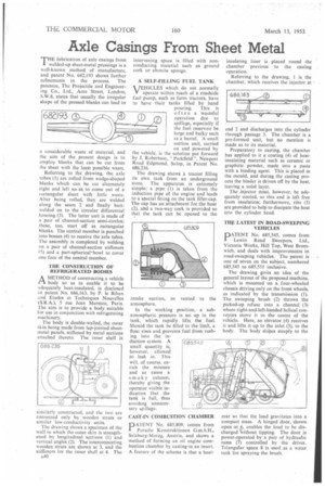
THE fabrication of axle casings from welded-up sheet-metal pressings is a well-known method of manufacture, and patent No. 682,193 shows further refinements in the process. The patentee, The Projectile and Engineering Co., Ltd., Acre Street, London, S.W.8, states that usually the irregular shape of the pressed blanks can lead to
a considerable waste of material, and the aim of the present design is to employ blanks that can be cut from the sheet with the least possible waste.
Referring to the drawing, the axle tubes (I) arc rolled from wedge-shaped blanks which can be cut alternately right and left so. aSio come out of a Jectangular sheet with little waste. After being rolled, they are welded along the seam '2 • and finally buttwelded on to the circular differential housing (3). The latter unit is made of a pair of channel-section semi-circles; these, too, start off as rectangular blanks. The central member is punched into bosses (4) to receive the axle tubes. The assembly is completed by welding on a pair of channel-section stiffeners (5) and a part-spherical•bowl to cover one face of the central member.
THE CONSTRUCTION OF REFRIGERATED BODIES
A METHOD of constructing a vehicle ./-1 body so as to enable it to be adequately heat-insulated, is disclosed in patent No. 686,163, by P. lc Bihan and Etudes et Techniques Nouvelles (S.R,A.), 5 rue Jean Mermoz, Paris. The aim is to provide a body suitable for use in conjunction with refrigerating machinery.
The body is double-walled, the outer skin being made from lap-jointed sheetnetal panels, stiffened by metal Sections quached thereto. The inner shell is similarly constructed, and the two are connected only by wooden struts or similar low-conductivity units.
The drawing shows a specimen of the wall in which the outer skin is strengthened by longitudinal sections (1) and vertical angles (2). The interconnecting wooden struts are shown at 3, and the stiffeners for the inner shell at 4. The A40 intervening space is filled with nonconducting material such as ground cork or ebonite sponge.
A SELF-FILLING FUEL TANK
VEHICLES which do not normally operate within reach of a roadside fuel pump, such as farm tractors, have to have their tanks filled by hand pouring. This is often a wasteful operation due to spillage, especially if the fuel reservoir be large and bulky such as a barrel. A small suction unit, carried on and powered by the vehicle, is the solution put forward by J. Robertson, " Parkfield ", Newport Road Edgmond, Salop, in Patent No. 686.236.
The drawing shows a tractor filling its own tank from an underground store. The apparatus is extremely simple; a pipe (1) is taken from the induction pipe of the engine and leads to a special fitting on the tank filler-cap. The cap has an attachment for the hose (2), aid a two-way cock is provided so that the tank can be opened -to the intake suction, or vented to the atmosphere.
In the working position,' a subatmospheric pressure is set up in the tank, which rapidly lifts the fuel. Should the tank be filled to the limit, a float rises and prevents fuel from rushing into the induction system. A small quantity is, however, allowed to leak in. This will, of course, enrich the mixture and so cause a sm ok y exhaust, thereby giving the operator visible indication that the tank is full, thus avoiding unnecessary spillage.
CAST-IN COMBUSTION CHAMBER
PATENT No. 685,809, comes from I Porsche Konstruktionen G.m.b.H., Salzburg-Morzg, Austria, and shows a method of forming an oil engine combustion chamber by casting-in an insert. A feature of the scheme is that a heat,
insulating liner is placed round the chamber previous to the casting operation.
Referring to the drawing, 1 is the chamber, which receives the injector at end 2 and discharges into the cylinder through passage 3. The chamber is a pre-formed unit, but no mention is made as to its material.
Preparatory to casting, the chamber has applied to it a coating (4) of heatinsulating material such as ceramic or graphitic powder, made into a paste with a binding agent. This is placed in the mould, and during the casting process the binder is driven off by the heat, leaving a solid layer.
The injector must, however, be adequately cooled, so this end is left free from insulation; furthermore, ribs (5) are provided to help to dissipate the heat into the cylinder head.
THE LATEST IN ROAD-SWEEPING VEHICLES
PATENT No. 685,545, comes from Lewin Road Sweepers, Ltd., Victoria Works, Hill Top, West Bromwich, and deals with improvements in road-sweeping vehicles. The patent is one of seven on the subject, numbered 685,545 to 685,551 inclusive.
The drawing gives an idea of the general layout of the proposed machine, which is mounted on a four-wheeled chassis driving only on the front wheels, as indicated by the transmission (1). The sweeping brush (2) throws the picked-up refuse into a channel (3) where right-and-left-handed helical conveyors move it to the centre of the vehicle. Here, an elevator (4) receives it and lifts it up to the inlet (5), to the body. The body slopes steeply to the
rear so that the load gravitates into a compact mass. A hinged door, shown open at 6, enables the load to be discharged Without tipping. The door is power-operated by a pair of hydraulic rams (7) controlled by the driver. Triangular space 8 is used as a water tank for spraying the brush.