


Floating Crankpin Weight to Damp Vibration
Page 36
If you've noticed an error in this article please click here to report it so we can fix it.
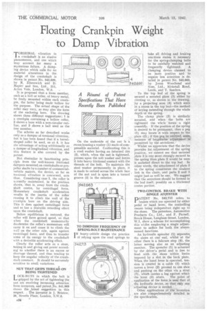
.TORSIONAL vibration in a crankshaft is an elusive phenomenon, and one which may account for many a mysterious failure. A damping device which calls for no material alterations in the design of the crankshaft is shown in patent No. 542,699, by R, Zclanowich and D. Napier and Son, Ltd. 211, Acton Vale, London, W.3,
It is proposed that a loose member, such as a ball or roller, of heavy metal, he freely mounted within each crankpin, the latter being made hollow for the purpose. The actual shape of the roller may vary, as may also the form of the enclosing bore. The drawing shows three different suggestions; 1 is a crankpin containing a hollow roller, 2 shows a bore with a non-circular outline, and 3 shows a ball used as the free member.
The scheme so far described works only as a damper of torsional vibration, but it has been found that if a barrelshaped roller be used, as at 4, it has the advantage of acting additionally as a damper of longitudinal vibration, and this feature is also covered by the patent.
Not dissimilar in functioning principle from -the well-known frictional dampers mounted on crankshafts or propeller shafts by a number of commercialvehicle makers, the device, so far as torsional vibration is concerned, acts thus., Considering case I, the roller is normally maintained, in the position shom'al, that is, away from the crankgraft centre, by centrifugal force. Momentary crankshaft acceleration results in the inertia of the roller causing it to climb the wall of the crankpin bore• on the driving side. This it does against centrifugal force and so has a desirable retarding effect upon the crankshaft.
Before equilibrium is restored, the roller will have gained speed, so that when the crankshaft momentarily decelerates the roller's momentum will carry it on and cause it to climb the -wall on the other side, again against centrifugal force, and thus to transfer some of its energy to the crankshaft with a desirable accelerating effect.
Clearly the roller acts as a store, taking in and giving out power according to whetlier there is an excess or shortage thereof, and thus tending to keep the angular velocity of the crankshaft constant. It should be extremely sensitive to small variations.
NUT THAT GRIPS THREAD ON BEING TIGHTENED
LOCR-NUTS in which the bolt is gripped by the act of tightening the nut. are receiving increasing attention from inventors, and patent .No. 541,969 shows the „latest suggestion in this
respect. The inventor is J. 'Bristow, 26, Neveirn Place, London, S.W.5,
AS'!
On the underside of the nut is a recess housing a washer (1) made of compressible material. Confronting this is a steel washer having an inturnecl rim (2), which, when the nut is tightened, presses upon the soft washer and forces it into heavy frictional contact with the threads of the bolt. To maintain the steel washer permanently in place, it is made to extend across the whole face of the nut and is spun into a turned ' groove (3) in the exterior.
TO DIMINISH FREQUENCY OF SPRING-BOLT MAINTENANCE I N heavy-kehicle design the practice of relying upon the road springs to
-take all driving and braking reactions makes it necessary for the spring-clamping bolts to be carefully watched and frequently tightened. A clamping' device claimed to be more positive and to
require less attention is de
4 tailed in patent No. 542,663,
by Jonas Woodhead and Sons, Ltd., Kirkstall Road, Leeds, and T. Sanders. '
To the top leaf of the spring is secured a serrated plate (3) either by riveting or, as shown in the drawing, by a projecting nose (4) which seats in a recess in the top leaf—the method of keying extending through the whole depth -of the spring.
The clamp plate (2) is similarly serrated, and when the bolts are tightened the • whcle 'forms 4 rigid -assembly. If the position of the spring is desired to be permanent, then a peg (1) may locate it with reSpect to the plate (2) ; if this peg be omitted; son% 3neastirO of lengthwise adjustment
• permitted by the serrations. Whilst we appreciate that the device provides for adjustment of the spring position, we cannot see that serrated plate 3 is any more strongly. secured to the spring than plate 2 would be were it socketed direct to the top leaf. In other words, the attachment of plate 3 to the spring constitutes the weakest link in the chain, and parts 2 and 8 might just as well be one. We suggest that the serrations should be formed in the leaf itself, possibly on a thickened centre portion.
TWO-CONTROL BRAKE WITH SINGLE ADJUSTER
PATENT No. 542,713 refers to brakes which are operated by either pedal or hand lever, the controlling means being independent right up to the shoes. The patentees, Automotive Products Co., Ltd., and F. Parnell, Brock House, Langham Street, London, W.1, show a scheme for accomplishing this whilst employing a single adjustment to suffice for both the abovenamed functions, An hydraulic spreader (1) separates, the shoes at one end, whilst at the other there is a fulcrum stop (4), the latter serving also as an adjusting member. The spreader (1) is actuated by the, driver's pedal and is free to float with the shoes within limits impored by a slot in the back plate. When the hand lever is operated, tension is created in a cable (3) which moves a lever. (2) pivoted to one shoe and pushing on the other via a strut (5), which carries a lug against which
the lever (2) abuts. The point of application of the .force is near, that of. the hydraulic device ; so that only' on. adjusting device is needed.
Other applications of 'the invention are also .comprehensively detailed 'in the specification,