


New Tipping Body on See-Saw Principle
Page 25
If you've noticed an error in this article please click here to report it so we can fix it.
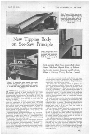
Hand-operated Chain Gear Draws Body Along Hinged Sub-frame Beyond Point of Balance. Hydraulic Device Ensures Gentle Drop. Maker is Utility Truck Bodies, Limited
A TIPPING body operated by gravity and employing an
unusual principle is being manufactured by Utility Truck Bodies, Ltd., The Close, Queen's Square, Lancaster. Accompanying illustrations show an example in which the scheme has been applied to a Thornycroft Sturdy equipped with a drop-sided lorry body and built for work under the Ministry of Supply.
It will be noted that the body proper and its supporting frame are constructed as two separate units, the latter being attached to the rear of the chassis frame by a hinged joint and the former being designed to slide in guides on the structure below it. Sliding movement is effected by hand,power, through the medium of two endless chains, whilst tipping, as mentioned earlier, is by gravity, the action being hydraulically controlled.
Running through the tipping trunnions is a cross-shaft, to the ends of which handles can be fitted. Its rotation is transmitted through bevel gears to a longitudinal shaft which, in turn, drives through a worm gear a shaft carrying the sprockets which are at the rear.
In operation, the chains draw the body proper rearwards relative to the intermediate frame to the point of balance. When this is reached the whole assembly " see-saws." A skid is provided at the rear Which, when it comes into contact with the ground, automatically unlocks and releases the tailboard, allowing the load to slide down gently as the vehicle draws away It is understood that packed goods, bricks and many consignments of a similar nature have been dropped in this manner, the load being left stacked on the ground almost exactly as it was while on the vehicle.
To ensure that the tipping motion is gradual, two hydraulic damping cylinders, which can be adjusted to give a range of different tipping speeds, are mounted in the chassis like tipping rams. They have a 20-in, stroke and are 3 ins, in diameter. These dampers can be locked to hold the body in any desired position as well as being used to control its motion. To prevent damage to the bodywork, immediately after the tailboard has been tripped, the weight of body and load is taken on a steel roller mounted at the extreme end.
A winch can be provided so that heavy indivisible loads may be hauled from the ground up the inclined floor, the body moving into its horizontal position so soon as the load crosses the centre of balance. Because the tipping angle is relatively small, some operators may desire to have a moving floor, and it is of note that one model is standardized with this equipment.
All the features already described are incorporated in this, with, in addition, a steel-slat floor which rolls up at the rear of the Vehicle. The moving floor, of course, can be used for dumping part loads, whilst it can be employed also to assist loading in the normal way, the contents of the vehicle gradually being wound forward as each line of the consignment is placed in position..
The rigid-floor machine we inspected has heavy-duty steel bodywork with a platform measuring 17 ft. by 7 ft. 6 ins. Steel angle plates are provided at the corners of the superstructure, and the whole is sturdily constructed, with the result that the weight is rather greater than usual. For ordinary duties, however, it would appear that the standard Utility body would be quite comparable with the figure for tippers generally.