


DAMPING AXLE OSCILLATIONS.
Page 18
Page 19
If you've noticed an error in this article please click here to report it so we can fix it.
A Study of the Problem of Suspension, Showing' the Advantage of the Snubber Acting Only as the Axle Falls.
By .THE kindness 0 an investigator into the subject of vehicle suspension-La man who prefers that his identity be not disclosed—we are enabled no describe a very interesting series of experiments in connection with the vibration imparted to a vehicle from road irregularities through pneumatic tyres, and the apparatus employed in the experiments.
Recording the Oscillations.
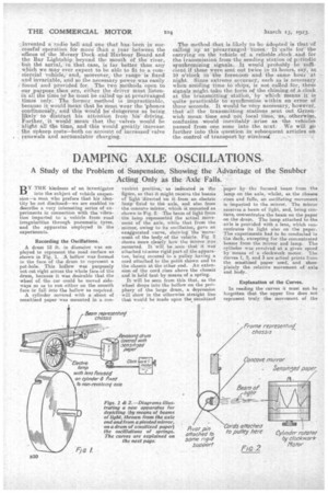
A drum 12 ft. in diameter was em ploj,ed to represent the road surface as shown in Fig. 1. A hollow was formed in the face of the drum to represent a pot-hole. This hollow was purposely not cut right across the whole face of the drum, because it was desirable that the wheel of the car could be moved sideways so as to run either on the smooth face or fall into the hollow as required.
A cylinder covered with a sheet• of sensitized paper was mounted in a eon
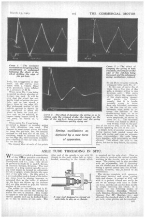
venient position;as indicated in the figtire, so that it might receive the beanis of light directed on it from an electric lamp fixed to the axle, and also, from the concave' mirror, which is mounted as shown in Fig. 2. The beam of light from • the lamp represented the actual movement of the axle, while that from the mirror, owing to its oscillation, gave an exaggerated curve, shOwiog the Move‘ • ment of the body, of the vehicle. Fig 2 shows more clearly how tho Mirror was mounted. It "will be seen that' it waS attached tO some rigid part of the apparatus, being secured to a pulley having a cord attached to the point shown and to the chassis at the other end. An extension of the cord rises above the chassis and is held taut by means of a spring.
It will be seen from this that, as the wheel drops into the hollow on the periphery of the large drum, a depression will show in the otherwise straight line that would be made upon the sensitized paper bythe focused beam from the lamp on the axle, whilst, as the chassis rises and falls, an oscillating movement is imparted to the mirror. The mirror receives a beam of light, and, being conCave, ooncentrates the beam on the paper on-the drum. The lamp attached to the axle is provided with a lens, which concentrates its light also on the paper. The experiments had to be conducted iu the dark, excepting for the concentrated beams from the mirror and lamp. The cylinder was revolved at a given speed by means of a clockwork motor. The .6urves 1, 2, and 3 are actual prints from the sensitized paper used, and show plainly the relative movement of axle and body..
Explanation of the Curves.
In reading the curves it most not be forgotten that the upper line does not represent truly the movement of the
-.body, but exaggerates it very much. All the curves were taken from a. vehicle fitted -with pneumatic tyres inflated to a pressure of 50 lb.
When curve No. 1 was being projected no shock absorber or it river, was used. It will be E•JE111 that the wheel has evid.ently tried to bottom the pothole, and so has struck a heavy blow to the edge (E). The undamped motion of the vehicle springs is shown by the oscilfation to allow the wheel to leave the road sur face, and, on the rebound, to Cure impart heavy impact blows to cord the road, as shown at C edge
and D.
When curve No. 2 was being
projected a damper or snubber acting in both directions was used. The damper to some extent allows the wheel to jump the pot-hole, but the -friction en-posed to the free rise of the axle, if anything, tends to increase the impact on the edge (E), -and transmits considerable vibration to the car body as shown by the line (PQ).
The impact blow at each of the points (C and D) is certainly reduced, compared with curve No. 1:'
In the case of curve No. 3 there was a free rise of the, axle, a damper acting hi one direction only. This curve clearly shows the superio:ity of the single-acting damper and proves the theory, namely, that it is fundamentally wrong to introduce any frictional resistance to the free rise of the axle. Attempts were made to increase the friction of the double-acting type, so as to obtain the same decrease in wave amplitude, as shown -in curve No. 3, The increased friction was found to effect a very serious result to the portion of the curve (PQ, curve No. 2) by heayily. opposing the rise of the axle.
A simple form of snubber consists of a strong leather belt carried round the back axle casing and over an adjacent frame cross-member, the ends being sewn together, with practically no slack allowed. This allows the -axle to rise above, but not to drop below, the normal line.