


Patents Completed.
Page 24
If you've noticed an error in this article please click here to report it so we can fix it.
An Improved Clutch.
J. W. Bowley, No. 3118, dated 7th February, 1912.—In the clutch mechanism described in this specification, a flanged collar is carried on one shaft, and a pair of annular plates are mounted in a suitable socket on the other shaft. The adjacent sides of these plates are tapered towards one another near the shaft, and a series of balls is mounted in carriers between these plates. The carriers can be moved radially; inward movement brings the halls into engagement with the two plates, and forces them apart, and also gives the necessary friction-grip on to the other part of the clutch. The lever controlling the ball carriers is spring. pressed outwards, the motion of the lever being limited by a spool sliding on the shaft, and having its inner face suitably shaped to give the lever certain definite positions according to the various requirements. In the position illustrated, the clutch is disengaged. By moving the spool on the right, towards the left, the lever is allowed to spring outwards somewhat, and thereby carries the balls inwards so that the clutch is in the friction-engaged position. Further movement of the spool towards the left releases the friction clutch, and engages the two shafts positively by a dogclutch.
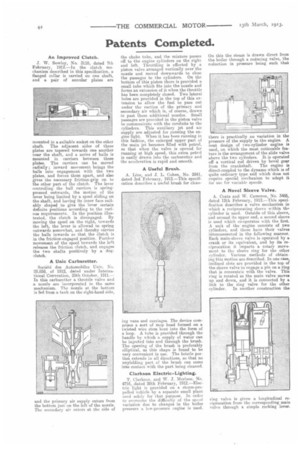
A link Carburetter.
Societe des Automobiles 1...Tnie, No. 23,858, of 1912, dated under Internatinnal Convention, 25th October, 1911.— In this carburetter a throttle valve and a nozzle are incorporated in the same mechanism. The nozzle at the bottom is fed from a tank on the right-hand side, and the primary air supply enters from the bottom just on the left of the nozzle. The secondary air enters at the side of the choke tube, and the mixture passes off to the engine cylinders on the right and left. Throttling is effected by a piston valve arranged vertically over the nozzle and moved downwards to close the passages to the cylinders. On the bottom of this piston there is provided a small tube which fits into the nozzle and forms an extension of it when the throttle has been completely closed. Two lateral holes are provided in the top of this extension to allow the fuel to pass out under the Ruction of the primary and secondary air which is, of course, drawn in past these additional nozzles. Small passages are provided in the piston valve to communicate with the conduits to the cylinders. This auxiliary jet and air supply are adjusted for running the engine light. When it has been running in this fashion, the enlarged upper part of the main jet becomes filled with petrol, so that when the valve is opened for running at high speed, this extra petrol is easily drawn into the carburetter and the acceleration is rapid and smooth.
A Useful Brush.
A. Line, and J. L. Cohen, No. 2841, dated 3rd February, 1912.—This specification describes a useful brush for clean
ing vans and carriages. The device comprises a sort of mop head formed on a twisted wire stem bent into the form of a loop. A tube is provided through the handle by which a supply of water can be injected into and through the brush. The opening of the brush is preferably elliptical, as this shape is found to be very convenient in use. The bristle portion extends in all directions, so that no unyielding part of the brush can come into contact with the part being cleaned.
Clarkson Electric-Lighting.
T. Clarkson, and W. J. Morison, No. 4716, -dated 20th February, 1912.—Electric light is provided on a steam-propelled vehicle by a separate small plant used solely for that purpose. In order to overcome the difficulty of the speed variation due to changes in the boiler pressure a low-pressure engine is used. On this the steam is drawn direct from the boiler through a reducing valve, the reduction in pressure being such that there is practically no variation in the pressure of the supply to the engine. A neat design of two-cylinder engine is used, on which the most noticeable feature is the arrangement of the slide valve above the two cylinders. It is operated off a vertical rod driven by bevel gear
from the crankshaft. The engine is direct-coupled to the dynamo which is of quite ordinary type and which does not require special mechanism to adapt it for use for variable speeds.
A Novel Sleeve Valve.
A. Coats and W. Cameron, No. 3485, dated 12th February, 1912.—This specification describes a valve mechanism in which a reciprocating sleeve within thP cylinder is used. Outside of this sleeve, and around its upper end, a second sleeve is used which co-operates with the first. A unit of the engine consists of two cylinders, and these have their valves interconnected in the following manner. Each main-sleeve valve is operated by a crank or its equivalent, and by its reciprocation it imparts a rotary movement to the sleeve ring for the other cylinder. Various methods of obtaining this motion are described. In one case, inclined slots are provided in the top of the sleeve valve to engage a pin on a ring that is concentric with the valve. This ring is rotated as the main valve moves up and down, and it is connected by a link to the ring valve for the other cylinder. In another construction the
ring valve is given a longitudinal reciprocation from the corresponding main valve through a simple rocking lever.