


New Braking System
Page 44
Page 45
If you've noticed an error in this article please click here to report it so we can fix it.
Prevents Skidding
THE avoidance of wheel-locking when braking on slippery roads reduces stopping distances and, even more important, ensures stability. This has been proved by a representative of The Commercial Motor in a series of braking tests . from 40 M.p.h., 50 m.p.h. and 70 m.p.h on prepared skid pads with a jaguar Mark 7 saloon ear . equipped with double-pad disc brakes and anti-skid units.
The braking system was an experimental unit based on the working principles Of the anti-skid brakes first produced for aircraft by the aviation division of the Dunlop Rubber Co., Ltd.; in 1952. It has been developed for vehicles and incorporates a hydraulic servo with pneumo hydraulic accumulators.
Although heavier commercial vehicles travel at far lower speeds than the average private car, it is more difficult to obtain ' a favourable deceleration rate under all conditions because of the high ratio of laden to unladen weight, and loss of steering control is generally far more critical. This particularly applies to semi-trailer outfits. .
According to a series of four tests on a flooded skid track by Dunlop test drivers with a ear having smooth tyres (giving a co-efficient of friction approximately equal to that of an icy surface) the Jaguar was stopped from. 35 m.p.h. in distances varying between 202 ft. and 207 ft. with the anti-skid device in use; in later runs with normalbraking the stopping distances ranged from 257 ft. to 269 ft.
In a test of the car equipped with tyres having a normal tread, on a curve of 150 ft. radius at a speed of approximately 38 m.p.h., the anti-skid system enabled outward deviation of the rear axle to be eliminated when braking whereas normal braking caused the back of the car to slide outwards.
In the case of heavier commerdal vehicles a relatively high load on tho rear wheels "hormally aids stability on slippery roads, but large variations in the front-to-rear load ratio created a particularly difficult braking problem. This would be overcome by employing the anti-skid system, and jack-knifing of an articulated. vehicle would be impossible.
Disc brakes are favoured for applications of the system because braking torque is proportional to the ' force applied, and hydraulic actuation is used because it enables application and release lag virtually to be eliminated. The system could be effectively applied to drum brakes if they were of a type which did not provide mechanical servo action, and it could be used in conjunc
thin with air-pressure brakes if the operating pressure were sufficient to obviate lag.
The normal master-cylinder type of hydraitlie system is not suitable for the application of the anti-„skid control because it could not be designed to provide compensation of the fluid exhausted by the anti-skid units when the hydraulic release valve is opened to prevent locking.
A new type of power brake system is being developed by the company, however, which 'gives normal makercylinder operation by dire& pedal action in the event of failure of the servo mechanism. In a normal operation the control valve Meters the pressure of the servo system to give a braking force proportional to applied load with virtually no movement of the pedal, the fluid exhausted from the anti-skid units being automatically compensated by make-up fluid.
In the event of power failure energystorage accumulators continue to provide servo action for the brakes, but when the accumulators are also exhausted the pedal moves downwards and engages a linkage actuating a conventional mastercylinder unit. At the same time the exhaust from the anti-skid units is cut off.
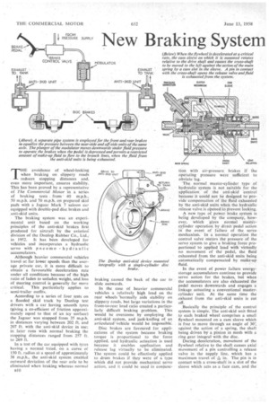
Basically the principle of the control system is simple. The anti-skid unit fitted to each braked wheel comprises a small flywheel mounted on a cam sleeve which is free to move through an angle of 30'; against the action of a spring, the shaft being driven by a pinion in mesh with a ring gear integral with the disc.
During deceleration, movement of the flywheel relative to the shaft causes axial movement of a pin controlling a release valve in the supply line, which has a
maximum travel of in. The pin is in contact with a cross-shaft in a slot of the sleeve which acts as a face cam, and the release valve is opened at a predetermined displacement of the flywheel relative to the shaft. This corresponds to the " optimum " rate of wheel deceleration, which is appreciably below the rate associated with wheel-locking.
Details of the mechanism include a clutch which transmits the drive of the flywheel to the cam Sleeve on the overrun. This allows a small amount of slip between the flywheel and sleeve if the rate of deceleration exceeds a limiting value, such as could result from momentary locking of the wheel during a prolonged bounce of the tyre.
Hydraulic pressure is relieved by the action of the flywheel in accordance with the maximum braking effort that can be applied on any surface without causing the wheels to lock. In effect, locking action is restored when deceleration is reduced below the critical rate.
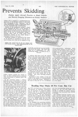
In the prototype 'system a Plessey hydraulic pump is chain-driven from the front of the engine crankshaft and fluid is supplied to a control valve operated by the brake pedal. This directs the fluid through units known as pressure modulators to the branch lines of the front and rear-wheel systems. The two wheel units of each axle are inter-connected at the front and the rear, so that the maximum operating pressure in the branch line is determined by the pressure in the antiskid unit, which is the first to operate if the brake adjustment is not uniform.
A modulator comprises a small cylinder, the plunger of which moves axially with the displacement of fluid td transfer the thrust to the brake line, initially to take up pad clearances and apply the brakes without any time lag. When the anti-skid release valve is in operation and the fluid pressure in the branch pipe is reduced, fluid flows from the control valve to the brake line through a restricter in the modulator which ensures that the line is kept full of fluid without wastage.
Two pneumo-hydraulic accumulators are employed to restore fluid energy and thus provide a surplus capacity for brake actuation if the pump is inoperative. A Lockheed automatic cut-out is fitted in the line between the pump and the brake control to allow the pump to idle when the accumulators are fully charged.
These are of the piston type in which the hydraulic pressure acts against corn. pressed air in the closed end of the cylinder. The rated operating pressure is 1,500 p.s.i.
Important to the validity of the test results is the system of instrumentation used to record the. results. Mounted in the boot of the test car is a 12-channel mirror-galvanomete. instrument winch records brake pressure in each unit and pressures in the control valve on photographic paper at intervals of 1/10th of a second. A tachometer generator is mounted on both rear wheels and provides a record of initial velocity.
Fore-and-aft deceleration is recorded by a decelerometer mounted on the floor in the boot. A road-marker unit is operated by an explosive charge fired electrically when a brake-mounted switch is closed, and thus enables stopping distances to be measured accurately. Calculations of average deceleration are based on records of initial velocity and stopping time.
The rate of deceleration of a wheel which is about to lock remains constant at all values of vehicle deceleration, braking effort and road speed. This explains why the anti-skid unit is as effective in the prevention of wheel locking when the vehicle is being braked at high speed on a slippery surface as it is when the surface is dry and the brakes are applied at a low speed.