


Novel Two-stroke Engine
Page 54
If you've noticed an error in this article please click here to report it so we can fix it.
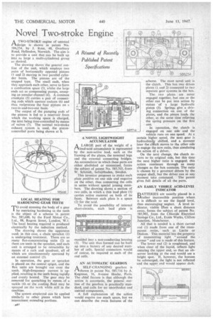
ATWO-STROKE engine of unusual• design • is shown in patent No. 586,254, by J. Rose, 48, Overbiiry Road, Hellesdon, Norwich. The aim is • to provide a unit that can be built up into as large .a rnutti-cylindered group as desired.
The drawing shows the general outline of the unit, which employs two pairs of horizontally opposed pistons (1 and 2) moving in two parallel cylinder bores. The pistons are of the stepped type. The small ends, when they approach each other, serve to form a combustion space (3), whilst the large .ends act as compressing pumps, sweeping an annular channel (4). A common crankpin (5) carries a pair of connecting rods which operate rockers (6) and thus reciprocate the four pistons on a two-in-and-two-out basis.
The output of the pumping ends of the pistons is fed to a reservoir from which the working space is charged, the inlet being time-controlled by means of valves (7). The normal two-stroke exhaust system is used, the pistoncontrolled ports being shown at 8.
LOCAL HEATING FOR HARDENING GEAR TEETH TO avoid stressing the body of a gear by restricting hardening to the teeth is the object of a scheme in patent No. 585,600, by the Ford Motor Co., Ltd., 88, Regent Street, London, WA. The local heating required is produced electrically by the induction method.
The drawing shows the apparatus used; in this case, a chain sprocket (I) is undergoing treatment. There are as many flux-concentrating units (2) as there are teeth in the sprocket, and each unit is arranged to be retractable by means of a rack and quadrant, all of Which are simultaneously operated by an external control (3).
In operation, the gear or sprocket is placed on the central spigot, and the flux units are brought out over the teeth. High-frequency current is applied, resulting in the teeth being rapidly and evenly heated. The gear may be removed for quenching by means of a tackle (4). or the cooling fluid may be sprayed on the work while still in the machine.
The system employed can be applied similarly to other pieces which have intermittent extending portions. A NOVEL LIGHTWEIGHT ACCUMULATOR
A A LARGE part of the weight of a
lead-acid actumulator is represented by the non-active lead, such as the framing of the plates, the terminal lugs and the external connecting bridges. An accumulator in which these parts are either abolished or minimized, forms the subject of patent No. 585,703, from W. Schmidt, Saltsjobaden, Sweden.
This inventor proposes to make each plate positive on one side and negative on the other, thus connecting the cells in series without special joining members. The drawing shows a section of two cells, in which a thin lead plate (1) carries active material on both of its faces. Between each plate is a space (2) for the acid.
To avoid the possibility, of internal short-circuits, each lead plate is
moulded into a non-conducting housing (3). The unit thus formed can be built up into a battery of any desired number of cells. Special connectors would of course, be required at each of the end cells.
AN AUTOMATIC GEARBOX A SELF-CHANGING gearbox is rtshown in patent No. 585,716 by A. Kegresse, 36, Avenue Hoche, Paris. The chtef feature is that although the action is automatic, the general outline of the gearbox is practically standard, and calls for no unorthodox and untried components.
A full explanation of the action would require too much space, but we can describe the main features of the scheme. The most novel unit is the clutch. This has two driven plates (I and 2) connected to two separate gear systems in the box.
The two plates are never engaged together, bat. one or the other can be put into action by rneans of a large hydraulic piston (3). Springs give a driving connection on one of the plates, and the piston loads the other, at the same time relieving the spring pressure on the first one.
In operation, the clutch is engaged on one side and the vehicle runs on one speed. At a certain higher speed, the next gear is hydraulical‘y shifted, and a moment later the clutch moves to the other side to engage the new ratio, thus simulating the action of a driver.
On the next change, the dutch reverts to its original side, but this time the next higher ratio is engaged; this action continues through as many changes as the 'box contains. The ratio is chosen by a governor driven by the output shaft, but the driver can at any moment take command. The patent gives full details of all the parts.
AN EASILY VISIBLE ACID-LEVEL INDICATOR
BATTERIES are usually placed in a rather inaccessible position where it is difficult to see the liquid level, thus encouraging neglect. A level indicator, visible fil'om a short. distance away, forms the subject of patent No. 585,902, from the Chloride Electrical Storage Co., Ltd., Exide Works, Clifton Junction, Manchester.
All that is needed is a short curved rod (I) made from one of the transparent resins, such as Lucite or Diakon. This material has the property of transmitting light "around the corner" and use is made of this feature.
The lower end (2) is roughened, and when clear of the liquid, reflectS light entering the upper end, so that an observer looking at the end would see a bright spot. If, however, the bottom be submerged, the light is not reflected and the upper end would appear dark.