


LONDON'S BUS BUILDERS MAKE TROLLEY-BUSES.
Page 12
Page 13
If you've noticed an error in this article please click here to report it so we can fix it.
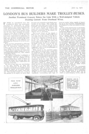
Another Prominent Concern Enters the Lists With a Well-designed Vehicle Drawing Current From Overhead Wires.
ITWILL be remembered that The Commercial Motor has consistently advocated the censtruction of railless trolley:buses in the works of 6ommercial motor manufacturers rather than in the works of tramway engineers. The latter, having only experience of vehicles which' run on rails, must naturally be 'tenthcapped in their efforts to design a chassis suitable for a vehicle to run on the common roads, which shall be satisfactory every way, whilst ot the same tinse being light and, therefore, involving the minimum of damage to road surfaces and absorbing the minimum of power in propulsion.
Since we first commenced to advocate the adoption of this line of policy on the part of commercial vehicle manufaetuners, we have had the pleasure of seeing it taken up by four concerns. The latest of these to produce for inspection a well-designed railless trolley-bus is the Associated Equipment Co., Ltd., makers of liondon's buses.
The raille.ss trolley-bus is primarily a power-driven chassis for use on ordinary road surface, and the question of the original source from which it draws its power has much less bearing upon the problems of design than would at first be generally imagined.
As will be seen from our reproduction of the plan drawing on page 519, the new trolley-bus, so far as its bare chassis is-concerned, is an ordinary motor chassis in respect of its frame, wheels, springs, steering gear, brakes, back axle, etc. The steering column can, owing to the absence of an engine, be taken right forward and mounted on the front crossmember of the frame. The weight imposed upon the front axle is that of the controller and resistance in place of that of the petrol engine, its radiator and clutch and universal joints, with all the necessary components of the engine, including electric generator.
The overall length of the chassis is 24 ft. 7. ins., and the overall width that is to say, over hub caps) is 7 ft. 01 ins., the width of the frame being 3 ft. 111 ins. at the front, widening out to 3 ft. 64 ins. at • the rear. The wheelbase is 14 ft. 11 ins., the wheels being shod with solid tyres, 1,010 mm. by 120 mm., singles on the front wheels and twins on the rear wheels. The chassis weight is 3 tons 5 cwt., and the unladen weight with a single-deck body to seat 36 passengers is about 4 tons 18 cwt.
With regard to the electrical equipment, there has always been a good deal of controversy on the matter of the employment of either two-motor equipment with series-parallel control and each having its own transmission to the back axle, or the employment of a single motor connected_ up to the worm drive by a universally jointed propeller shaft. The Associated Equipment Co. have chosen the latter system as, whilst. there is a. small sacrifice of electrical efficiency, it is superior to the two-motor equipment from the standpoint of the upkeep of a road vehicle and, of course, is cheaper in first cost. The electric motor has been supplied by the B.T.H. Co., and is one of that concern's latest examples of the ventilated, commutating pole type of tramway motor, being capable of standing up to big overloads withoutatrouble or breakdown on the commutator or elsewhere.
So far as the transmission is concerned, the employment of a single motor means a mare simple chassis and a higher mechanical efficiency by the employment of one worm gear as against two there is also less running friction and, therefore, a greater ability to coast on declines. Acceleration is also better, so that., on the whole, the single motor snakes for greater economy in running.
With regard to control, the system may be considered separately with regard to its two parts. The first part is the footoperated drum controller, so designed that the forward motion accelerates the vehicle notch by notch on the controller. On releasing the foot, the controller conies back to the off position. It is prevented from going back into reverse position by an automatic locking lever, which latter has to be moved by hand should reversing be required. The reverse is operated by a heel pedal, which is positively connected to the forward speed 'pedal; hence either pedal can be returned from its driving position to the neutral position by foot pressure on the opposite pedal, which affords a safety. device in the event of either return spring failing to operate.
In comparison with the movements which the driver of a petrol-driven bus has to make in order to operate the petrol vehicle, the operation. of a trolley-bus is quite simple, because there are no clutch or gear-changing levers, and all the driver has to do is to depress his foot control pedal notch by notch until he arrives at the position where the current is fully on. With regard to steering and brake operation, these matters are similar to the petrol bus. The second portion of the control is entirely automatic. Its purpose is automatically to increase the power o speed acceleration of the vehicle. At the end of the motor shaft there is mounted a governor, which operates a switch when the critical speed is reached at which acceleration would normally fall off. This switch, by means of a contactor, induces a shunt resistance across the motor field winding, and the effect is to increase the acceleration to the extent of about a 10 per cent, improvement. on the average speed during a notarial run, The effect of the governor is, therefore, the opposite to that of a governor on the petrol vehicle, which limits the engine speed and, theref ore, the vehicle speed. In the case of the trolley-bus the governor enables the motor.to run more rapidly when conditions are such as to render this safe and desirable, whilst the motor is able to exert, its full torque at any speed below the critical speed—a very important feature. The motor is rated at 33.5 b.h.p. and is spring-suspended from the chassis. Ths rheostat is of the unbreakable grid type and is also spring-supported. It is fixed to the chassis and protected 1mm readsplash and rain by a suitable tray and cover, so arranged as not to impede the .ventilation. High-grade material is used in the wiring, and the cables throughout are heavily taped together end supported on the chassis by hard wood blocks. The two control booms are mounted on a ball-bearing base, both booms swinging from a common centre and being balanced by heavy external springs, adjustable to give the necessary contact pressure on the trolley wires.