


Novel Pneumatic Suspension System
Page 62
If you've noticed an error in this article please click here to report it so we can fix it.
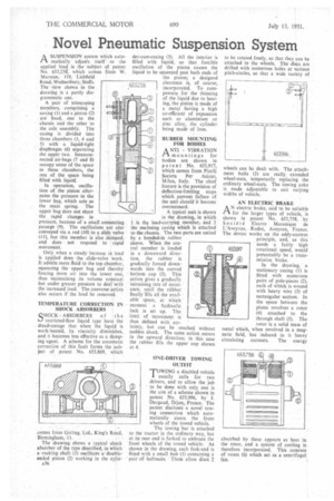
ASUSPENSION system which automatically adjusts itself to the applied load is the subject of patent No. 653,258; which comes from W. Marston, 119, Lichfield Road, Wednesbury; Staffs. The view shown in the drawing is a partly diagrammatic one.
A pair of telescoping members, comprising a casing (1) and a piston (2) are fixed, one to the chassis and the other to the axle assembly. The casing is divided into three chambers (3, 4 and 5) with a liquid-tight diaphragm (6) separating the upper two. Interconnected air-bags (7 and 8) occupy some of the space in these chambers, the rest of the space being filled with liquid.
In operation, oscillation of the piston alternates the pressure in the lower bag, which acts as the main spring. The upper bag does not share the rapid changes in pressure, because of a small connecting passage (9). The oscillations are also conveyed via a rod (10) to a slide valve (II), but this member is also damped. and does not respond to rapid movement.
Only when a steady increase in load is applied does the slide-valve work. It admits more fluid to the top chamber, squeezing the upper bag and thereby forcing more air into the lower one, thus maintaining its volume constaat but under greater pressure to deal with the increased load. The converse action also occurs if the load be removed.
TEMPERATURE CORRECTION IN SHOCK ABSORBERS
CHOCK-ABSORBERS of the sJ restricted-flow liquid type have the disadvantage that when the liquid is work-heated, its viscocity diminishes, and it becomes less effective as a damping agent. A scheme for the automatic correction of this fault forms the subject of patent No. 653,869, which comes from Girling,'Ltd., King's Road, Birmingham, 11.
The drawing shows a typical shock absorber of the type described, in which a -rocking shaft (1) oscillates a: doubleended piston (2) working in the cylin a36 der-cum-easing (3). All the interior is filled with liquid, so that forcible oscillation of the piston causes the liquid to be squeezed past both ends of the piston; a designed clearance is, of course, incorporated. To compensate for the thinning of the liquid due to beating, the piston is made of a metal having a high co-efficient of expansion such as aluminium orzinc alloy, the cylinder being made of iron.
RUBBER MOUNTING
FOR BODIES ANTI VIBRATION 1-3. mountings for bodies are shown in paten t No. 653,917, which comes from Pirelli Societa Per Azioni, Milan, Italy. The chief feature is the provision of deflection-limiting stops which prevent failure of the unit should it become overstressed.
A typical unit is shown
in the drawing, in which 1 is the load-carrying member, and 2 the enclosing casing which is attached to the chassisThe two parts are united by a bonded-in rubber sleeve. When the central member is loaded in a downward direction, the rubber is gradually forced downwards into the curved bottom cup (3). This action gives a gradually increasing rate of resistance, until the rubber finally fills all the available space, at which moment a hydraulic lock is set up. The limit of movement is thus defined with certainty, but can be reached without sudden shock. The same action occurs in the upward direction; in this case the rubber fills the upper cup shown at 4.
ONE-DRIVER TOWING OUTFIT
TOWING a disabled vehicle usually calls for two drivers, and to allow the job to be done with only one is the aim of a scheme shown in patent No. 653,996, by J. Dargaud, Dijon, France. The patent discloses a novel towing connection which automatically steers the front wheels of the towed vehicle.
The towing bar is attached to the tractor in the ordinary way, but at its rear end is forked to embrace the front wheels of the towed vehicle. As shown in the drawing, each fork-end is fitted with a small hub (1) containing a pair of ballraces. Thee allow discs 2 to be rotated freely, so that they can be attached to the wheels. The discs are drilled with numerous holes at various pitch-circles, so that a wide variety of wheels can be dealt with. The attachment bolts (3) are really extended wheel-nuts, temporarily replacing the ordinary wheel-nuts. The towing yoke is made adjustable to suit varying widths of vehicle.
AN ELECTRIC BRAKE
AN electric brake, said to be suitable for the larger types of vehicle, is shown in patent No. 653,758, by Socid t C Electro Mecanique de L'Aveyron, Rodez, Aveyron, France. The device works on the eddy-current principle, and, as this needs a fairly high 6539t7 rotational speed, would presumably be a transmission brake.
In the drawing, a stationary casing (I) is fitted with numerous pairs of pole-pieces (2), each of which is wound with heavy wire (3) of rectangular section. In the space between the plates revolves a rotor (4) attached to the through shaft (5). The rotor is a solid mass of
which, when revolved in a mag metal field, has induced in it heavy netic circulating currents. The energy absorbed by these appears as heat in the rotor, and a system of cooling is therefore incorporated. This consists of vanes (6) which act as a centrifugal fan.