 1
1 2
2 3
3 4
4 5
5 6
6 7
7 8
8 9
9 10
10 11
11 12
12 13
13 14
14 15
15 16
16 17
17 18
18 19
19 20
20 21
21 22
22 23
23 24
24 25
25 26
26 27
27 28
28 29
29 30
30 31
31 32
32 33
33 34
34 35
35 36
36 37
37 38
38 39
39 40
40 41
41 42
42 43
43 44
44 45
45 46
46 47
47 48
48 49
49 50
50 51
51 52
52 53
53 54
54 55
55 56
56 57
57 58
58 59
59 60
60 61
61 62
62 63
63 64
64 65
65 66
66 67
67 68
68 69
69 70
70 71
71 72
72 73
73 74
74 75
75 76
76 77
77 78
78 79
79 80
80 81
81 82
82 83
83 84
84 85
85 86
86 87
87 88
88 89
89 90
90 91
91 92
92 93
93 94
94 95
95 96
96 97
97 98
98 99
99 100
100 101
101 102
102 103
103 104
104 105
105 106
106 107
107 108
108 109
109 110
110 111
111 112
112 113
113 114
114 115
115 116
116 117
117 118
118 119
119 120
120 121
121 122
122 123
123 124
124 125
125 126
126 127
127 128
128 129
129 130
130 131
131 132
132 133
133 134
134 135
135 136
136 137
137 138
138 139
139 140
140 141
141 142
142 143
143 144
144 145
145 146
146 147
147 148
148 Power-assisted Steering
Page 108
If you've noticed an error in this article please click here to report it so we can fix it.
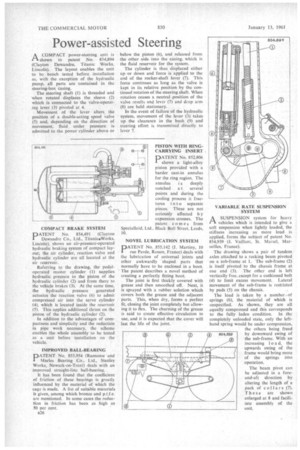
1-1 A COMPACT power-steering unit is shown in patent No. 854,894 (Clayton Dewandre, Titanic Works, Lincoln). The layout enables the unit to be bench tested before installation as, with the exception of the hydraulic pump, all parts are contained in the steering-box casing.
The steering shaft (1) is threaded and when rotated displaces the sleeve (2) which is connected to the valve-operat ing lever (3) pivoted at 4. .
Movement of the lever alters, the position of a double-acting spool valve (5) and, depending on the direction of movement, fluid under pressure is admitted to the power cylinder above or COMPACT BRAKE SYSTEM 110ATENT No. 854,491 (Clayton Dewandre Co., Ltd., Titanic•Works, Lincoln), shows an air-pressure-operated hydraulic braking system of cornpact layout; the air cylinder, reaction valve and hydraulic cylinder are all located at the air reservoir.
Referring to the drawing, the pedaloperated master cylinder (1) supplies hydraulic pressure to the piston of the hydraulic cylinder (2) and from there to the vehicle brakes (3). At the same time, the hydraulic pressure generated actuates the reaction valve (6) to admit compressed air into the servo cylinder (4), which is located inside the reservoir (5). This applies additional thrust on the piston of the hydraulic cylinder (2).
In addition to the advantages of compactness and simplicity and the reduction in pipe work necessary, the scheme enables the whole assembly to be tested as a unit before installation on the vehicle.
IMPROVED BALL-BEARING
PATENT No. 855,954 (Ransome and Marks Bearing Co., Ltd., Stanley Works, Newark-on-Trent) deals with an improved straight-line ball-bearing,
It has been found that the coefficient of friction of these bearings is greatly influenced by the material of which the cage is made. A list of suitable materials is given, among which bronze and p.t.f.e. are mentioned. In some cases the reduction in friction has been as high as 50 per cent.
1326 below the piston (6), and released from the other side•into the casing, which is the fluid reservoir for the system.
The cylinder is thus displaced either up or down and force is applied to the end of the rocker-shaft lever (7). This force continues as long as the valve is kept in its relative position by the continued rotation of the steering shaft. When rotation ceases a neutral .position of the valve results and lever (7) and drop arm (8) are held stationary.
In the event of failure of the hydraulic system, movement of the lever (3) takes up the clearance in the bush (9) and steering effort is transmitted directly to lever 7.
PISTON WITH RLNGCARRYING INSERT
PATENT No. 852,806 shows a light-alloy piston provided with a harder cast-in annulus for the ring region. The
annulus i s deeply notched a t several points and during the cooling process it fractures into separate pieces. These are not seriously affected b y expansion stresses. The patent comes from Specialloid, Ltd., Black Bull Street, Leeds, 10.
NOVEL LUBRICATION SYSTEM
DATENT No. 855,142 (I. Martiny, 10 rue Payee, Rouen, France) deals with the lubrication of universal joints and other awkwardly shaped parts that normally have to be enclosed in a boot. ' The patent describes a novel method of creating a perfectly fitting boot.
The joint is first thickly covered with grease and then smoothed off. Next, it is sprayed with a rubber solution which covers both the grease and the adjacent parts. This, when dry, forms a perfect fit, closing the joint completely but allowing it to flex. The churning of the grease is said to create effective circulation in use, and it is expected that the cover will last the life of the joint, VARIABLE RATE SUSPENSION SYSTEM
ASUSPENSION system for heavy vehicles which is intended to give a soft suspension when lightly loaded, the stiffness increasing as more load is. applied, forms the subject of patent No, 854,939 (.I. Vailiant, St. IVIarsel, Marseilles, France).
The drawing shows a pair of tandem axles attached to a rocking beam pivoted on a sub-frame at 1. The sub-frame (2) is itself pivoted to the chassis frame at one end (3). The other end is left vertically free, except for a cushioned bolt (4) to limit excess movement. Lateral movement of the sub-frame is restricted by pads (5) on the chassis.
The load is taken by a number-of springs (6), the material of which is unspecified. As 'shown, they are all equally compressed and this corresponds to the fully laden condition. In the completely unloaded state, only the lefthand spring would be under compression, the others being freed by downward swing of the sub-frame, With an increasing I o a d, the upwards swing of the frame would bring more of the springs into operation.
The beam pivot can be adjusted in a foreand-aft direction by altering the length of a pack of collars (7). These are shown enlarged at 8 and facilitate assembly of the unit.