


Promising Refinement in Gas-producer Design
Page 40
If you've noticed an error in this article please click here to report it so we can fix it.
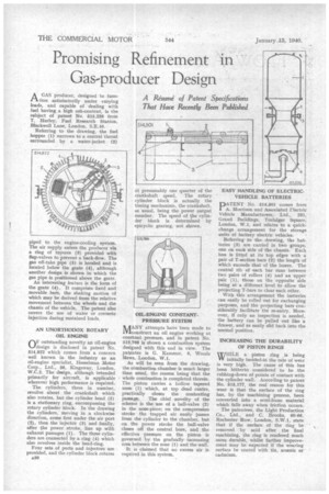
AGAS producer, designed to func, tion satisfactorily under varying loads, and capable of dealing with fuel having a high ash-content, is the subject of patent No, 515,226 from T. Hurley, Fuel Research Station, Blackwell Lane, London, S.E.10.
Referring to the drawing, the fuel hopper (1) narrows to a central throat surrounded by a water-jacket (2)
piped to the engine-cooling system. The air supply enters the producer via a ring of tuyeres (3) provided with flap-valves to prevent a back-flow. The gas off-take pipe (5) is hooded and is located below the grate (4), although another design is shown in which the gas pipe is positioned above the grate.
An interesting feature is the form of the grate (4). It comprises fixed and movable bars, the shaking motion of which may be derived from the relative movement between the wheels and the chassis of the vehicle. The patent also covers the use of water or creosote injection during sustained loads.
AN UNORTHODOX ROTARY OIL ENGINE
(-IF outstanding novelty an oil-engine L./design is disclosed in patent No. 514,822 which comes from a concern well known in the industry as an oil-engine specialist, Hesselman Motor Corp., Ltd., 56, Kingsway, London, W.C.2. The design, although intended primarily for aircraft, is applicable wherever high performance is required.
The cylinders, three in number, revolve about the crankshaft which also rotates, but the cylinder head (5) is a stationary ring, encompassing the rotary cylinder block. In the drawing the cylinders, moving in a clockwise direction, come first under the air port (2), then the injector (3) and finally, after the power stroke, line up with exhaust passages (1). The three cylinders are connected by a ring (4) which also revolves inside the head-ring.
Four sets of ports and injectors are provided, and the cylinder block rotates A30 at presumably one quarter of the crankshaft speed. The rotary cylinder block is actually the timing mechanism, the crankshaft, as usual, being the power output member. The speed of the cylinder block is determined by epicyclic gearing, not shown.
OIL-ENGINE CONSTANT. PRESSURE SYSTEM
MANY attempts have been made to construct an oil engine working at constant pressure, and in patent No. 513,766 is shown a combustion system designed with this end in view. The patentee is G. Kammer, 6, Woods Mews, London, W.1.
As will be seen from the drawing, the combustion chamber is much larger than usual, the reason being that the whole combustion is completed therein. The piston carries a hollow tapered nose (1) which, at top dead centre, practically closes the conhecting passage. The chief novelty of the scheme is the use of a ball-valve (2) in the nose-piece; on the compression stroke the trapped air easily passes from the cylinder to the chamber, but on the power stroke the ball-valve closes off the central bore, and the effective pressure on the piston is governed by the gradually increasing area between the nose (1) and the wall.
It is claimed that no excess air is required in this system. EASY HANDLING OF ELECTRICVEHICLE BATTERIES
PATENT No. 514,501 comes from A. Morrison and Associated Flectric Vehicle Manufacturers, Ltd., 231, Grand Buildings, Trafalgar Square, London, W.1, and relates to a quick change arrangement for the storage units of battery electric vehicles.
Referring to the drawing, the batteries (3) are carried in two groups, one on each side of the chassis. Each box is fitted at its top edges with a pair of T-section bars (2) the length of which exceeds that of the boxes. The central rib of each bar runs between two pairs of rollers (4) and an upper pair (1), those on the opposite side being at a different level to allow the projecting T-bars to clear each other.
With this arrangement the batteries can easily be rolled out for exchanging purposes, and the projecting bars considerably facilitate the re-entry. Moreover, if only an inspection is needed, the battery can be pulled out like a drawer, and as easily slid back into the normal position.
INCREASING THE DURABILITY OF PISTON RINGS
TS/HiLE a piston ring is being YY initially bedded-in the rate of wear is very high. The cause of this has been hitherto considered to be the rubbing-down of points of contact with the cylinder wall. According to patent No. 515,177, the real reason for this wear is that the surface of the ring has, by the machining process, been converted into a semi-loose material which falls away when friction occurs.
The patentees, the Light Production Co., Ltd., and C. Brooks, 60-66, Rochester Row, London, S.W.1, state that if the surface of the ring be removed by acid after the final machining, the ring is rendered much more durable, whilst further improvement may be expected if the wearing surface be coated with tin, arsenic or cadmium.