


A Development in Trolley-bus Control
Page 50
If you've noticed an error in this article please click here to report it so we can fix it.
TlEmrecently granted patent (384,433) of Mr. J. G. Smithson, of Oakdale, Alvechurch, Worcestershire, should be of great interest to those concerned with the operation of trolleybuses, as it provides a means whereby a driver can feel, by the resistance of a pedal, what is occurring in the traction motor.
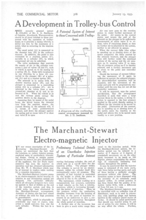
The usual pedal (A) is connected to the rheostat arm (B) in the ordinary manner. In addition, the pedal is also connected to a reaction piston (C), movable in a cylinder (D), to which compressed air can be admitted.
The valve mechanism that controls the supply of air to the cylinder comprises a pair of valves (E and )0, each of which is moved on to its seating by a spring (II, I). Each valve is,actuated in one direction by a lever (J) connected to the plunger (K) of a solenoid (L) and to a tension spring (M).
The solenoid ia in series with the electric traction motor (N), and the plunger is connected to a controlling piston (0) in a cylinder (P), Air is admitted to the valves from a compressed-air chamber at Q and is exhausted at II. When the vehicle is at rest the various parts occupy the position shown in the diagram.
Assuming that, by means of the pedal lever, the driver moves the rheostat • arm from the position shown, the • current flowing in the solenoid will, if in excess of some predetermined amount, pull down the plunger against the spring and so cause valve F to close and valve E to open Air can now pass to the reaction piston to resist further movement of the pedal. Air passes to the control piston and causes the pull of the solenoid on the plunger to be sufficiently counteracted to allow valve E to reclose, valve F remaining closed, so that no further air is admitted to the system, neither is air allowed to escape.
When the current -falls (due either to speeding up or slowing down of the motor armature) the force exerted by the solenoid weakens, and the plunger rises still farther under the combined actions of the spring and the air pressure on 0, causing valve 1' to open. The air pressure acting on C is thereby relieved, and a further movement can be given to the pedal and controller arm (B).
Should the increase of current following the movement of B again be sufficient to operate the solenoid plunger, the above-described operation will be repeated, and the movement of the pedal and arm will be progressively controlled until the arm has out out all the controller resistance, It will be apparent, says the patent specification, that the arrangement described is such that when a large current flows in the motor, a strong reaction is oppesed to the foot pressure applied to the pedal, thereby making it difficult for the rheostat to be moved by the pedal. Diminution of the current, due to speeding up or slowing down of the motor, eases the reaction on the pedal and allows this to be moved more readily to a new position.