


AN AUTOMATIC VARIABLE SPEED GEAR.
Page 28
If you've noticed an error in this article please click here to report it so we can fix it.
A Rdsumiof a Recently Published Patent Specification.
IN a specification which reads like an eight-page essay on variable gears, the patent No, 225,735of the Reece TransmisSion, Go., of Boston, U.S.A.; is described. As set forth, this invention seems to possess Many advantages over efforts in this direction which have been made in the past. Unlike some gears of this class, no ratchet is employed, neither is there any intermittent driving of the car by a number of hammer blows or jerks. The speed is described as automatically adjusting, itself to the resistance to the driven •member through hill-climbing or inertia when Starting.
A control of the road speed of the ear can be maintained by means of the usual throttle. When the apparatus is operating at what might be called top gear, all parts run round as if they were a solid mass.
It is said that no clutch is needed, as, when the en, gine apeed is reduced by means of the throttle below a certain paint, the gear no longer transmits power to the driving wheels. The gear is said to act, when required, as a brake in either direction, to act as a reverse and to form a lock when it is desired to prevent the car being moved.
Th design of this gear appears to entail the employment of centrifugal force in a manner which seems to us to be entirely new. The action is not easy to describe, and this fact probably accounts for the length of the specification.
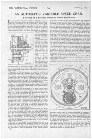
Broadly, the gear resembles a planetary gear in so far that the driving member (A), Fig. I, is attached to the crankshaft, and is provided with four studs (B), on which revolve drums of special construction, which will be described later.
The central shaft (D) represents the driven member, and attached to its right-hand end is a flange which is intended to represent the universal joint through which power is transmitted to the final drive.
A central gear (E) is anchored to an miter casing which supports a ball bearing on the right: A second central gear (F) is mounted on a sleeve which runs on the driven shaft (D). It will be noticed that the planetary wheels do not mesh with the central gears directly.
Fig. 2 is a sectional view through the broken line 2, 2, and shows the intermediate pinions (G and H) which connect up • the planetary wheels with the central wheels. The inventor gives his reason for introducing these wheels, but we have not space for it here. We now come to the drums (C) which form the Max of the invention. From. Pig. 1 it will be seen that the drums are composed of two separate parts, an outer 1C) and an inner (CT), both of which are provided with gearwheels, which, through the intermediate pinions, mesh with the gears on the central shaft.
Those who are familiar with planetary gears will know that, were the parts (C and Cl) free to revolve independentlj of each other, the gear (CT) would roll round the anchored gear (E) without imparting any motion to the gear (F). Now, this is exactly what happens when the engine speed is low. A close inspection of C and CT in Fig. 2 will show their peculiar construction. Internal paddles are formed in C, while ,external paddles are formed on GT. A heavy fluid (mercury) is descried as being used partly to fill the spaces between these paddles.
The action of centrifugal force is relied upon to set up .a retardation of revelutional movement around its own axis of the outer drum (0). It is well known that centrifugal force for a given mass increases as the square of rotary speed, and advantage is taken of this fact, as the spaces between
n44
the paddles are made of such a sliar.3 that they will discharge their contents at a certain point owing to centrifugal force. This point is that which is nearest to the centre of the whole gear. At this point the contents, when discharged, are taken into the 'spaces formed in the inner portion (CT), where it is taken charge of and brought to a point farthest from the centre of the whole apparatus, wiiere it is discharged again into the outer member (C); By this means the rotary Motion of G is retarded by having to move a-stream of heavy fluid, divided into separate portions, from the outer portion of the apparatus towards the centre against the pull due to centrifugal form. It will be seen that, as the speed of revolution of the whole gear increases, the centrifugal force becomes so great that C is prevented from revolving on its own axis, consequently the whole mass revolves practically as a solid Piece, and power is transmitted as through a direct shaft. The return of the fluid by means of CT is a positive action, and does not depend on the relative velocities of the driven and driving members.
Fnlly to describe the action of the reverse gear would take more space than we have available, but it is accomplished by means of the bevel gear shown, and by the sliding dog clutch, which, when at one end of its stroke, causes a forward drive, and when at the other extremity gives a reverse. When as shown in Fig. 1, it is in the locked position and the car cannot then be moved in either direction. • The specification mentions the fact that a braking effect CAD be obtained from this gear, but the actual means employed are not made very clear.
Of all the inventions which have recently appeared in which the object has been the prevision of a. gear -ivhich will auto matically adjust itself to various conditions of resistance', this appears to be one of the most ingenious and promising. The absence of anything in the nature of intermittent imPulses' and the fact that, when at its highest ratio, or what may be termed top gear, the Whole mass moves substantially as a solid, seem to place the invention on a higher plane than most efforts in this direction.
, It may be said that power is wasted in gathering the heavy fluid front the outer part of a revolving drum towards the centre, but the inventor claims that this power is restored to the drive by means of the wheel which carries it towards the outside of the circle again.