


HYDRAULIC TRANSMISSION.
Page 26
If you've noticed an error in this article please click here to report it so we can fix it.
A Résumé of Recently Published Patents.
The advantages which belong to an efficient hydraulic transmission are widely recognized. UP to the present, notwithstanding the many efforts which
have been made to obtain them, they have remained unattainable, owing to the fact that the necessary degree of efficiency in the transmission has not been achieved. With the ideal form of transmission, the ratio between the speeds of revolution of engine and road wheels would automatically vary with the resister-ice enconntered by the wheels, and an infinite variation of the ratio would be possible,. ranging from a direct drive to the free engine position. The principal disabilities from whieh previous transmissions of this nature have suffered, and which, together with, minor troubles, have been, sufficient to lower the efficiency of the gear to that -point at which the advantages conferred have failed to be sufficient compensationtlor the losses incurred, are two in number. The necessarily small dimensions of the mechanism have involved the use of high fluid pressures, and it has hitherto 'been practically impossible to provide against the inevitable leakage which resulted.
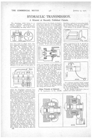
Dr. Hele-Shaw claims to have overcome these difficulties satisfactorily in a design which is described in specifications No. 135,524 and No. 135,799. Imagine the engine flywheel to carry a cylindrical casing of about the same diameter as itself. Disposed round the inside of the easing is a number of open-ended dashpot cylinders; they are horizontal or, more correctly, their axes are parallel to that of the engine shaft. There are two pistons to each da.shpot, so arranged that their open ends face one another, and an enclosed compartment is formed in each case by one cylinder and its two pistons. Ports and passages wain the casing allow of communication between each cylinder and the next in rotation, and valves in these passages provide for the regulation of the freedom of communication between the cylinders. On the driven shaft, which may be in effect the C46
propeller shaft of the chassis, is keyed a pair of discs, disposed, not at right angles to the shaft, but closer to one another at one side than at the other. Only a thin liner • intervenes between these discs, which are called awash plates, and the outer ends of the dashpot pistons. Now. presuming the casing, cylinders, etc., full of liquid, and the passages wide open, so that no resistance is offered to the movement of the liquid from cylinder . to cylinder, it will be understood that, as the flywheel and casing revolve, the dashpot pistons will move freely in and out, undcr the influence of the swash plates, pumping the fluid from cylinder to cylinder. If the ports be closed en
tirely, no movement of the pistons will be possible, and the swash plates will be carried round at the same speed as the engine flywheel, giving a direct drive. By partial throttling of the paSsages, different ratios can be obtained.
.A..force pump, drawing from an external supply, and delivering to the casing through non-return valves, maintains the fluid pressure within the transmission and compensates for leakage. For the free engine position, means are provided for releasing the pressure altogether withinthe casing, when the liners which intervene between the pistons of the dashpots and the awash plates are drawn together 'by springs, leaving the casing and cylinders free.
Other Patents of Interest.
F. W. Lanchester, in No. 135,582, describes a method of constructing builtup crankshafts, which are then adapted for use with roller or ball -bearings. The feature of the paraffin vaporizer,
which is described by H. R. Ricardo in No, 135,598, is that the exhaust gas, which is used to dilute the charge as, wall as to' warm the mixture, is controlled-so that at full loads less is supplied for the latter purpose and more for' the former, and vice versa for light loads.
The aim of 31. Birkigt, in patent No. . 135,698, has beeu to suspend the engine in the frame, so that there is no unsightly aperture 'under the bonnet, giving access either to the ground or to the undershield.
Two adjacent sprocket wheels coupled by.a piece of double roller chain is the form of universal joint which is patented by the Birmingham and Midland Motor Co., Ltd., in No. 135,765.
In No. 135,609 is described a form of audible and visible indicator.