


Live Axles for Commercial Vehicles.
Page 5
Page 6
Page 7
If you've noticed an error in this article please click here to report it so we can fix it.
A Resume ot an Interesting Paper Read Yesterday before the I.A.E. by Mr. Geo. W. Watson, Member of Council.
It is with much pleasure that we publish extensive extracts from an interesting paper which was read yesterday by Mr. Geo. W. Watson, ALLMech.E., before the Institute of Automobile Engineers, of the Council of which he is a member.
We have, as is our practice, carefully considered the paper and extracted for publication purposes those parts which we consider to be likely to be of most use to the readers of THE COMMERCIAL Mom& This is obviously better practice than to reproduce without. comment or selection any paper read before a scientific. body, just as it is presented.
Controlling Factor in Back-axle Design.
Mr. Watson, after suitable introductory remarks, proceeds promptly to state the bases upon which he considers that all good back axle designs should be lo and e,d
In all calculations for axles the author takes as a basis the limit of adhesion between plain solid tiros and the curfare of the road. He accepts this limit as 0.4 of the imposed weight on the back tires (including, the wheels themselves), and as this is about the worst condition to be met with on any macadamized road, it has been fetind to meet the ease better than working either from the power end of the transmission, or from the braking effort. A factor of safety of not less than seven on the yield point of the material should be allowed for the load-bearing parts, and not less than four On the transmission shafts and gears. It is, of course, desirable to keep down the unsprung weight as much as possible, but on no account should this consideration be allowed to outweigh others, as it has still to be proved that unsprung w.cight, as weight, has any real effect upon the wear of either lire or road.
What is M?ant by "Floating and Semi-Heating , Axles."
A very useful definition of the mue.h-abused and readily-quoted descriptions of various types. of live axles is included. We are indebted to the author for a much-needed statement-on this subject.
There appears to be much diversity of opinion as to the meaning of the term " floating," " semi-floating," and " non floating," as applied to live axles. These terms, which the author believes are of American origin, are tuU.Ch used in im• pressive tones by many salesmen and others who have obviously no conception of their meaning; they often couple . them with varying' arrangements of spring mounting, torque and thrust. rods, etc., in a most perplexing mannerThe interpretations which the author proposes to use throughout . this paper, are as follows:—
['Noting axle.—An axle in which the wheel-driving. or • differential, shafts transmit only 'torsional effort. Seini=floafing aide. An axle in which the wheel-driving shafts partly, or wholly, support the bending. stresses due to the gear drive plus the torsional stresses, but which are relieved of all. bending stresses due to the imposed load and the tractive resistance.
Non-floatipq ax1,3.—An axle in which the differential shafts wholly or partly take the combined bending stresses due to the imposed load and the tractive resistance. Otis the torsional stresses due to the transmiSSion Of power to the wheels.
Types of "Solid-Forging' Axles.
A dip into early commercial-vehicle history is made-T and certain ascertained weaknesses of pioneer:'designs are recorded.
The author will not venture to make any assertion as to who was the first to use an axle Of this tyP.a. The",141and Co., however, have long used one form on their petrol vehicles, In their early axles the road wheels were journaIled upon
hollowed, or tubular, extensions from a cradled forging, in the dip of which the housing for the driving and differential geming was mounted. The wheel-driving shafts, projecting from ea.ch side of the housing passed through the tubular extensions of the forging, to couplings on the wheel hubs. There were certain objections to this form, arising from the dip, as any deflection of the axle was accompanied by a corresponding end load on the wheel-driving shafts, with consequent. nromentai.v excessive side loads upon the. ball bear
ings within the driving gear housing. This difficulty eas partly overcome by adding a separate compression, or arched, member above the casing, of somewhat similar dimensions to the dip below. A better form of this axle, in the author's opinion, is the Pagefield, -which is also noteworthy for the accessibility of its working parts.
For axles in which the axis of the differential gear is coincident with that of the-road. wheels, it is convenient to make the axle forging in the shape of a double-shafted banjo, in the manner long used by. the Maudslay Co. The general impression is that this company was the first to use this f•trin of axle, but the author'recalls that in 1906, or 1907, Thornycrofts showed such a worm-driven axle at Olympia..
The Limitations of the Horizontal Banjo Type.
The banjo design of,axle structure has been the subject of much attention in drawing offices dUring.recent years, and we are at one with the author in his plea for the adoption of'less radical changes of section than are evident in many existing designs.
This kind of axle when laid upon its side is not in its beet position for taking imposed loads, and is liable; to excessive deflection under such loads. A-few makers have tried*to overcome this by deepening the ring-shapechenlargement, but that does not help matters, as the-modulus•of section through the centre of the axle is already generally,much•greater than
at any other point. The allowance of' more metal at the junction of the tubular extensions, with, the ring is of much greater import than depth of-section of the ring, as it is at the junctions, or " throats," thatidefleetion, and sometimes fracture, occurs. In the Empire axle' weakness has been overcome by making.the throats start at a tangent. from the periphery of the ring, and die ont, into the extensions with easy curves. The extensions, also; are made free from sudden changes of diameter on the outside, and the bore is simply a rotigh drilled clearance hole, free from expensive counterbores. The little extra metal at the "throats " does not add much to the weight of the finished axle, lout greatly increases the resistance to deflection. Comparative tests upon this axle and one in which the extensions ran intothe ring at a radius of 4 ins, showed that, for the same diameter of extension and depth of ring, and the. same Wheel and spring centres, the former deflected only one-sixth as much as tht latter.
Although the horizoutal disposition of the banjo is not the most favourable so far as imposed-vertical loads are concerned, it is not necessarily the worst, having regard to all the. conditions which have to be met. For instance, the horizontal thrust from a central torquethrust member, rine to the tractive resistsince, may conceivably impose a greater bending moment on the axle than,that due to the vertical loads. Such conditionswould arise whenever the vehicle be driven, with full load, up gradients steeper than 1 in 7.
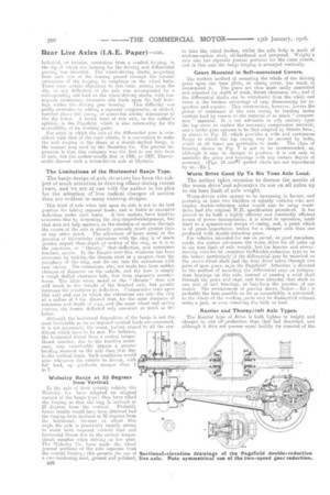
Wolseley Banjo at 25 Degrees from Vertical.
In the axle of their subsidy vehicle, the Wolseley Co. have adopted an original variant of the banjo type; they have tilted the forging so that the ring is inclined at 25 degrees from the vertical. Probably better results would have been obtained had the forging been inclined at 25 degrees from the horizontal, because at about this angle the axle is praetically equally strong to resist both imposed vertical loan and horizontal thrust due to the central torquethrust member when driving on low gear. The Wolseley Co. have made the wheel journal portions of the axle separate from the central forging; this permits the use of a ease-hardening steel, ground and polished, B26
to take the wheel bushes, whilst the axle body is made of medium-carbon steel, oil-hardened and tempered. Wrigley's axle also ha.s separate journal portions for the same reason, and in this axle the banjo -forging is arranged vertically.
Gears Mounted in Self-contained Covers.
The modern method of mounting the whole of the driving gears upon one base plate, or casing cover, has much to recommend it,. The gears are thus mom easily assembled and adjusted for depth of mesh, thrust clearance, etc-, and if the differential shafts ca-n he withdrawn from the wheel end there is the further advantage of easy dismounting far inspection and repairs. This construction, however, lowers the power of resistance, of the axle casing to bending under vertical load by reason of the removal of so much "compression" material. It is not, advisable to rely entirely upon the top cover to replace the necessary compression material, and a better plan appears to be that adopted by Dennis Bros., as shown in Fig. 10, which provides a wide and continuous flange to which the top casing may be secured by bolts,
which at all times are preferable to studs. The class of housing shown in Fig. 7 is not to be recommended, as, although it may be cheaper to produce, it is not easy to assemble the gears and bearings with any certain degree of accuracy. [Figs. 10 anda7 quoted above are not reproduced by us.—Ere] Worm Drive Good Up To Six Tons Axle Load.
The author takes occasion to discuss the merits of the worm driveand advocates its use on all axles up to six tons limit-of axle weight.
Worm-driven axles appear to be increasing in favour, and probably at least two builders of subsidy vehicles who now employ double-reduetion axles would also be using wormdrive had the original W.D. specification permitted. It has proved to be both a highly efficientand constantly efficient means of power transmission; it is silent in operation, lends itself to a symmetrical design of casino, and, a point which is of great importance, makes for a -cheaper axle than one produced with double-reduction gears.
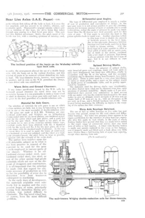
For vehicles intended,for use on paved, or good macadam, roads, -the author advocates the worrn drive for all axles up to six tons limit of axle weight, but for heavier and slower. moving vehicles, he considers theidouble-reduction type to be the better, particularly'if the differential gear be mounted on the crown-wheel shaft; and the final drive taken through two pairs of spur gears, as,in the Pagefiele Attention is directed to the method of mounting the differential cage on independent bearings on this axle, instead of passing a solid shaft through the gears and cage, and then carrying that shaft on one pair of ball bearings, its has been the practice of one maker. The arrangement of gearing shown [below.—En.] is probably the best-possible as far as accessibility is eoncerned, ae`the whole-of the working parts may be dismantled without using a jack, or even removing the body or load.
Karrier and Thornycroft Axle Types.
The Karrier type. of drive is both lighter in weight and cheaper in cost of, production than that last described, and although it does not possess equal facility for removal of the
parts without first taking off the body or load, it is none the less practical, and has proved to be reliable, efficient, and reasonably quiet. Thornyeroft's original subsidy vehicle axle was a variation of this type, the drive being., first taken through spur gearing to a final bevel gear drive. This axle had two distinct advantages: firstly, the pitch speed of the bevels was low, with a resulting quietness of running; and,
treonilly; the arrangement allowed, the use of a double banjo axle, with the banjo set in tho vertical direction, and this ailowed all parts to be removed without disturbing the body or load. The large-diameter bevels however, were expensive to produce, and as soon as the W.D.1 permitted the change, a worm-driven axle was substituted.
Worm Drive and Ground Clearance.
If any future specification issued by the W.D. calls for ircreased ground clearance the worm drive may not he ateeptable, because it is not practicable to make a worm wheel as small in diameter, for a. given gear ratio and load, as may be given to the final gearwheel of a double-reduction axle.
Material for Axle Gears.
The selection of materials for axle gears is one on which Nerious °pillions are held, but it may be\interesting to know that in one of the most successful of double-reduction axles ell the. gears are made of K.E. 805. Wolseleys use casehardened nickel-steel, and Wrigleys use an oil-hardening chrome-nickel steel for the. bevel pinions, case-hardened nickelsteel for the crown wheel and spur pinion, and a good tire steel for the spur wheel. With regard to the pitch of the gear teeth for an axle of the three-toss subsidy vehicle type, xcellent results have been, obtained ith No. 5 diametral pitch for the bevels and No. 4 for the spur gears, all of in -lute shapeshape with the standard angle of pressure. In the case of worm drive it is usual to make the worm of nickel-steel, cese-hardened, ground and polished, and the wheel of a higherade phosphor-bronze, the pitch being as large as possible, ceisistent with the strength of the worm shaft.
The author here touches upon the mill debatable subject as to what is
the best practice in respect of the
inaterial to be used for thegear v. heels employed in various parts of the chassis. Whether it be oil hardened chrome-nickel steel, -casehardened nickel steel, tire steel, or
any of th?, other special high-grade materials which are now at, the disposal of designers and constructors, a it is all-important that the selection be made with due regard for ultimate accuracy of production as well as for the possibility of error due todistortion from heat treatment subsequent to machining.
,tri the early days of development-, the materials available were relatively few in number and the everpresent bogey of noise, principally arising from distortion during prod!zetion, was indeed difficult to eliminate. The big bevel wheel has, of course, been the most difficult problem.
Diiferentialgear Angles.
The type of differential gear employed is largely a matter of cost of production and convenience of design. In the span-gear type it is not always possible to give the planetary pinions the necessary number of teeth of suitable size to avoid undercutting, unless the angle of pressure be made very much larger' than the 20 degrees now most generally used for this class of gear. If that angle is exceeded the load on the pinion spindles leads to-eapid wear. Another objection is that in this type there is double the amount of backlash present in the bevel type, duo to the aggregate clearances between bearings and gear teeth, and this in time
is liable to become serious. With the bevel type it is quite possible to allow a large pitch of tooth and an ample number of teeth in the pinion, combined with a low angle of pressure. End-thrust is always present with the bevel type of gear, but it is not diflieult to cope with it.
Splined Driving Shafts.
Since the adoption of splined shafts, with broached gears and couplings, many old weak spots in: axles have disappeared, but many new difficulties, chiefly in connection with the fit of the splines. and the necessary corrections due to distortion during heat-tieament, have taken their place.. There is great need for a very close interchange. of views on these points, and a paper on the subject would no doubt prove of considerable value, and be greatly appre elated by members. , .
The materials used for driving shafts vary considerably, and often depend upon what-can be obtained more than upon questions of greatest suitability. Shafts made of-3 per cent. nickel-steel have proved very satisfactory in hard serviCe with one maker who has the material heat-treated by the steel: maker to give an ultimate. tensilestrength of 54 tons and-an elastic limit of 47 tons per sq. in., With an elongation of 25, per cent. on 2 ins., and a Brinell hardness test of. 248. Thus treated before machining the difficulty in regard to the warping of the splines has been overemne.
Plain Axle Bearings Retained.
The use of ball or roller bearings on live axles has now become very general, except for the road wheels and differential bearings. For these two purposes there appears to be ample justification for the retention of plain bearings ; especially does this apply to road wheels, in the hubs of which floating bushes have proved that they are muds better suited to the rough usage of commercial service than any tried form of reller or ball bearing. A wheel with floating hushes is easily and quickly replaced in the event of tire damage, and if properly made and fitted such a. bush offers very little more friction than a ball-bearing hub of -equal load capacity, except when starting from rest.