


Patents Completed.
Page 20
If you've noticed an error in this article please click here to report it so we can fix it.
Sunbeam Valve Gear. A Novel Starting Gear. Four-wheel Driving and Steering. A Duplex Air-admission Valve.
Copies of complete specifications of the patents published on this page can be obtained from the Sales Branch, Patent Office, Holborn, WC., at the cost of sixpence for each specification.
SUNBEAM MOTOR CAR CO., LTD., L. COATALEN and H. C. N. STEVENS, No. 3324, dated 2nd March, 1915.—This specification relates to valve-operating mechanism of the type in which the
cams are provided with two grooves side by side with a cross. connection between them at one point, and a slipper on the tappet-rod is arranged to travel round each of the grooves successively. According to this invention each cam is mado to operate two separate valves.
A shoe for the cam is mounted on a valve-lifter which operates on the tappets, instead of allowing the cam to act directly on the tappets. This lifter slides in a bracket which is pivoted so that it can he swung from side to side to follow the slipper as it moves laterally from one groove to the other. This motion is used to transfer the valve-lifter from one to the ether of the two tappets which it operates.
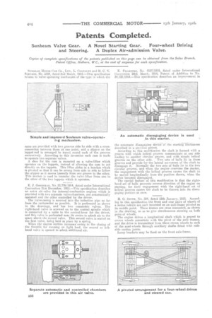
E. J. GOODYEAR, No. 22,776/1914, dated under International Convention 31st December, 1913.—This specification describes an extra air-valve for internal-combustion engines which is provided with two separate valve-chambers, one automatically operated and the other controlled by the driver. The valve-casing is screwed into the induction pipe as far from the carburetter as possible. It is perforated as shown in the drawings, and has two concentric valves. The right-hand valve is screwed on to the central spindle which is connected by a cable to the control-lever for the driver, and this valve is perforated near its centre to admit air to the space above the second valve. This second valve is seated on the first valve, being held in place by a spring. When the engine suction increases owing to the closing of the throttle for running on light load, the second or lefthand valve is opened to admit additional air. E. FILLETTAZ, No. 4557/1915, dated under International Convention 24th March, 1914, Patent of Addition to No. 24,122/1914.—This specification describes an improvement in the automatic disengaging device of the starting mechanism described in a previous patent.
According to this modification the shaft is formed with a groove with which helical grooves communicate at one side leading to another circular groove, and with simple helical
grooves on the other side. Two sets of balls lie in these grooves and provide for the lateral movement of the shaft to disengage it. Normally the two sets of balls lie in the twe circular grooves, and when the engine overruns the starter, the engagement with the helical grooves causes the shaft to be moved longitudinally from the position shown, when the device becomes disengaged. The special feature of this modification is that the righthand Set of balls prevents reverse direction of the engine on starting, for their engagement with the right-hand set of helical grooves causes the shaft to be thrown into its disengaging position at once.
H. G. SMITH, No. 504, dated 12th January, 1915. According to this specification the front and rear pairs of wheels of a motor vehicle are each mounted on an axle-frame pivoted at its middle point. These frames are cross connected, as shown in the drawing, so as to give simultaneous steering on both pairs of wheels. The engine drives a longitudinal shaft winch is geared to crown wheels concentric with the pivot of the axle frames, and the drive is transmitted from these crown wheels to each of the road-wheels through auxiliary shafts fitted with suitable cardan joints. Lamp brackets may be fixed on the front axle-frame.