


HINTS ON MAINTENANCE.
Page 30
Page 31
If you've noticed an error in this article please click here to report it so we can fix it.
How to Get the Best Out of a Vehicle, to Secure Reliability and to Avoid Trouble
CONTRIBUTIONS are invited for this page from fleet Managers, drivers, garage foremen, and mechanics, works staff and draughtsmen, and will be paid for on a generous scale. Every system, make, and type of commercial motor vehicle is being dealt with, and the matter, should be written with a view to the disclosure of workshop and garage practice in the maintenance of a vehicle. It often happens that even a normal practice, or a practice peculiar to a particular type of vehicle, is not generally known. Expedients and suggestions for overcoming roadside and other troubles are covered in the following page, dealing with letters from our driver and mechanic readers. Communications should be add:essed to " The Editor, The Commercial Motor, 7-15, Rosebery Avenue, London, E.C.1."
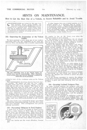
332.—Improving the Suspension of the Vulcan Engine.
We have received a letter from one of our readers regarding Hint isicr. 325, published in our issue for January 23rd, and dealing with a trouble experienced
owing to wear of the crankcase arms on the Vulcanengine. Our correspondent mentions that he has had simi, lay trouble. He points out that the rear engine brackets form part of a U-section girder, reaching from side to side of the chassis. The bolts in the engine had been loose for some time, and the fibre packing had been baminered away, with the reiult that the aluminium feet had worn very considerably. They were repaired by securing to each of them, by
two 4in. setscrews, a piece of brass plate, and bedding these down to the irregular shape by means of a hammer and punch. The plates and feet were then made homogeneous by means of aluminium solder, and were aftEirwards,,levelled to the correct face.
The short bolts were replaced by longer ones fitted with strong compression springs, and new fibre packings were inserted. This arrangement has proved entirely successful.
333.—Preventing Oiling-up in Ford Engines.
A good deal of trouble is caused in Ford lorries, and to a lesser degree in Ford vans, by oiling-up of the front. two sparking plugs. Most users know that this trouble is.caused by oil being trapped in the front part of the crankcase when the machine is dftcending a hill, and, as the throttle is likely to be closed, the oil has every chance of passing the pistons. Ford ton lorries are the worst offenders, because the engine is low at the front, even when the machine stands on level gromid. In the opinion of our contributor the oil should be carried as high as the upper cock, and to enable this to be done without causing oiling-up trOubles the following procedure can be adopted.
Remove the pistons from the engine and turn a chamfer on the bottom edge of the last groove. The depth oNthis chamfer at the edge of the groove should not exceed 1-32 in., so that it will not take away too much bearing surface from the ring. Its breadth should be about in., and at equal distances round it eight 3-32-in. holes should be drilled.
It is advisable to fit new rings, but the lower two rings should be pinned with the slots at opposite sides and in line with the gudgeon pin. Care must be taken that the word "Ford," which is stamped on the edge of the rings, faces the top of the piston, as each ring has a slight taper so that the bottom edge acts as an oil scraper. • •
The object of the chamfer on each piston is to .provide a channel for the escape of -oil, whichwould otherwise pile up below the bottom ring and ba tumble to find an escape past the close-fitting skirt. The oil then tends to close the ring by its wedging action and to escape upwards.
On a ton-truck which used to be a heavy consumer of lubricating oil, and which was treated in this manner, the amount now utilized is about one pint per 100 miles.
It is not always necessary to remove the pistons of the third and fourth cylinchrs, providing the compression is good and that oiling-up does not occur in them.
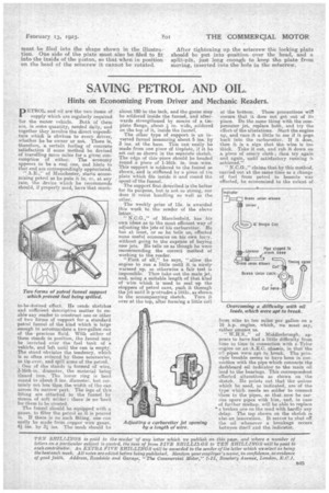
334.—Securing Leyland Gudgeon Pins.
In some Leyland engines the gudgeon pins are located in position by setscrews whichare prevented from turning by passing a, split-pin through the head of each. Occasionally the effect of vibration has caused these split-pins to wear, with the, result that the setscrews have worked loose, and the gudgeon pins have scored the cylinders. This fault can be overcome by utilizing a piece of sheet steel about 12 S.W.G. as a lockling plate. In this must be drilled a hole slightly smaller than the diagonal of the square-headed setscrew. This hole
must be filed into the shape shown in the illustration. One side of the plate must also be filed to fit into the inside of the piston, so that when in position on the head of the setscrew it cannot be rotated. After tightening up the setscrew the locking plate should be put into position over the bead, and a split-pin, just long enough to keep the plate from moving, inserted into the hole in the setscrew.