


Patents Completed.
Page 20
If you've noticed an error in this article please click here to report it so we can fix it.
TWO-CYCLE ENGINE,--Thomson.— No. 19,663, dated 3rd September, 1907.— This invention consists of two working cylinder (A, Al), and two compression cylinders (B, 131). Air :nlet ports (E, El), which are valveless, are formed in the walls of the compression cylinders ; each valve is located at some distance from the base of the cylinder. Ports (F, Fl) are formed in the walls near the outer ends of the compression cylinders. Another port (E2) is formed in the surface of the trunk conneeting the compressing pistons ; this one being arranged to work over an opening (G) which passes through the walls of the compression cylinders. The opening (G) communicates with a scavenging way (II) formed in the walls of the working cylinders. At the centre of the scavenging way (H) provision is made for establishing communication with a mixture-supply way (K) which extends in opposite directions and terminates in admission ports (K1, K2). When the engine is operating, the upward stroke of the compressing piston (D1) will cause a supply of air to be drawn into the compression cylinder (B1) after the working head (D1) has passed the inlet port (El), and, on the return stroke, the entrapped charge of air will be compressed, compression continuing until the travel of the compressing piston establishes communication between the ports (F2, F1). When this has been established, the compressed air will flow to the central way (G) and charge the scavenging and mixture-supply ways (H, K), assuming that the valve (N) is in the position shown in Figure 3. In conjunction with this action, the working piston (C), in completing its effective stroke, first uncovers the scavenging port (Hl) simu'taneously with the exhaust port, so that the air admitted to the cylinder (A) helps to expel the waste products of combustion. At a later stage, the piston (C) uncovers the mixture-supply port (K1) and a stream of air flows through the apertures in M, to the way (K). Thus, the air, in passing the delivery nozzle (L), takes up a charge of
hydrocarbon, which passes to the working cylinder (A) after the scavenging has been in progress, and charges the working cylinder. The piston of this cylinder then commences its compression stroke, in the initial part of which the admis sion, and exhaust, ports are closed. The cycle of action is thus completed, and it is alternately repeated in opposite ends of the engine, COUPLINGS FOR RADIATOR TUBES.—Thomson.—No. 758, dated 11th January, 1907.—Flexible connections
are provided for connecting the ends of the circulating tubes, or piping, to the water tanks of motor-vehicle radiators. A socket piece (A) is formed with projecting lugs (B) having in-turned flanges (C, C) adapted to engage with resilient webs, or flanges (D, D), on the clip (E). This clip consists of a thin metallic plate (c) having an orifice through which the tube (F) passes, and a flanged edge which, on each side (D), is detached from the plate and is sufficiently resilient to spring under the corresponding catch (C) on the socket piece (A) when the clip is pressed into position over the rubber ring (G). The rubber ring fits in the soc
ket (A) around the tube (F) and forms a flexible, but watertight, joint between the tube (F) and the tank part of the radiator.
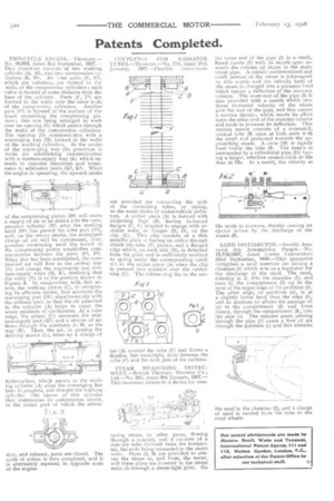
STEAM MEASURING INSTRUMENT.—British Thomson Houston Co.; I.td.—No. 635, dated 9th January, 1907.— This invention relates to a device for mea suring steam, or other gases, flowing through a conduit, and it consists of a mercury tube inclined from the horizontal, the ends being connected to the steam main. Pipes (2, 3) are provided to convey the steam to, and from, the meter, and these pipes are inserted in the steam main (I) through a steam-tight joint. On
the inner end of the pipe (2) is a small, flared nozzle (7) with its mouth open towards the column of steam in the main steam pipe. A certain predetermined and small portion of the steam is intercepted by this nozzle and the velocity head of the steam is changed into a pressure head which causes a deflection of the mercury column. The inner end of the pipe (3) is also provided with a nozzle which produces increased velocity of the steam post the end of the pipe, and this causes a suction therein, which exerts its effect upon the other end of the mercury column and tends to increase its deflection. This suction nozzle consists of a truncated, conical tube (9) open at both ends w:th the small end presented towards the approaching steam. A cone (10) is rigidly fixed inside the tube (9). The nozz:e is surrounded by a cylindrical pipe (11) having a larger, effective cross-section at 12a than at 13a. As a result, the velocity at
13a tends to increase, thereby causing an ejector action by the discharge of the nozzle (9).
SAND DISTRIBUTOR.—Societh Anonyme des Automobiles Peugot.—No. 19,716/1907, dated (under Convention) 22nd September, 1906.—This apparatus comprises a sand reservoir (m) having a chamber (b) which arts as a regulator for the discharge of the sand. The sand, entering at d, fills the chamber (1), and rises in the compartment (2) up to the level of the upper edge of the partition (b). The other edge, or partition (a), is at a slightly lower level than the edge (b), and an aperture (c) allows the passage of air to the compartment (2) and from thence, through the compartment (3), into the pipe (e). The exhaust gases passing through the pipe (f) cause a flow of air through the aperture (e) and this disturbs
the sand in the chamber (2), and a charge of sand is carried from the tube to the road wheels.